2. Initial Setup
Before beginning software configuration, please see the Hardware Setup section for specific racking and connection information.
Depending on the degree of pre-configuration requested from iXsystems, most of the initial TrueNAS® setup might already be complete.
Note
Always perform the initial TrueNAS® setup in consultation
with your iXsystems Support Representative. iXsystems Support can
be contacted at truenas-support@ixsystems.com. Be sure
to have all TrueNAS® hardware serial numbers on hand. They are
located on the back of each chassis.
2.1. Out-of-Band Management
Before attempting to configure TrueNAS® for out-of-band management, ensure that the out-of-band management port is connected to an appropriate network. Refer to the guide included with the TrueNAS® Storage Array for detailed instructions on how to connect to a network.
Connect the out-of-band management port before powering on the TrueNAS® Storage Array.
In most cases, the out-of-band management interface will have been pre-configured by iXsystems. This section contains instructions for configuring it from the BIOS if needed. The same settings can be configured using the instructions in IPMI.
Press F2 at the splash screen while the TrueNAS® Storage Array
is booting to access the system BIOS. This opens the menu shown in
Figure 2.1.1.
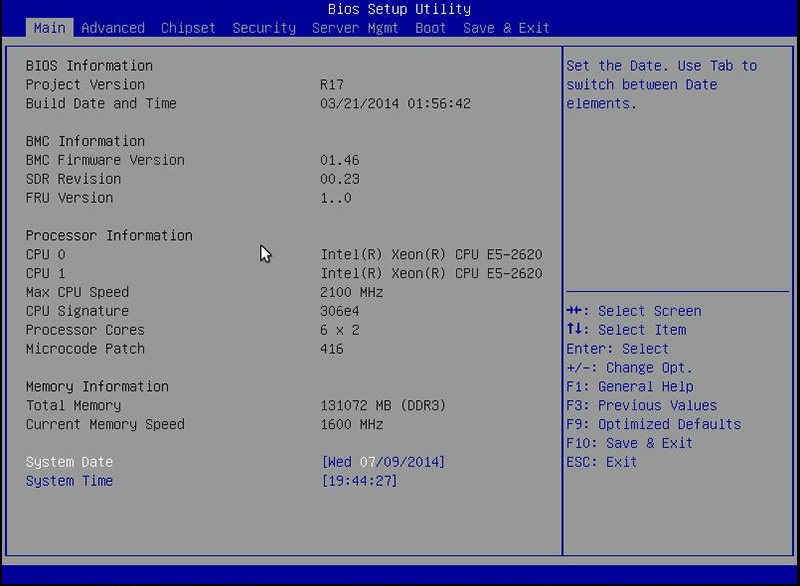
Fig. 2.1.1 Initial BIOS Screen
Navigate to the Server Mgmt menu and then BMC LAN Configuration, as shown in Figure 2.1.2.
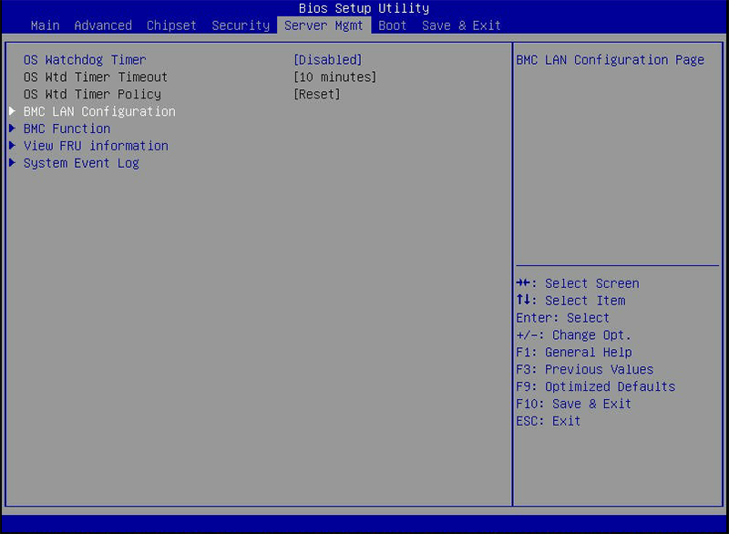
Fig. 2.1.2 Navigate to BMC LAN Configuration
When using DHCP to assign the out-of-band management IP address, leave the Configuration Source set to Dynamic in the screen shown in Figure 2.1.3. If an IP has been assigned by DHCP, it is displayed.
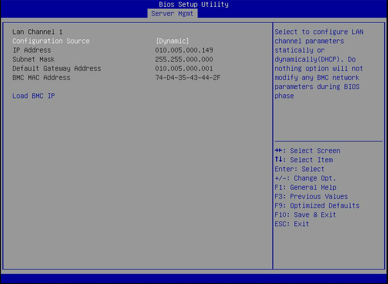
Fig. 2.1.3 Configuring a Dynamic IP Address
To assign a static IP address for out-of-band management, set the Configuration Source to Static, as shown in Figure 2.1.4. Enter the desired IP Address into the IP Address setting, filling out all four octets completely.
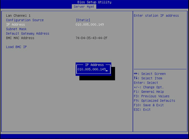
Fig. 2.1.4 Configuring a Static IP Address
Next, enter the Subnet Mask of the out-of-band management network subnet. An example is shown in Figure 2.1.5.
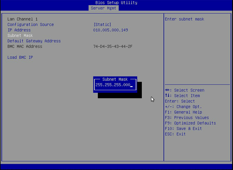
Fig. 2.1.5 Entering the Subnet Mask
Finally, set the Default Gateway Address for the network to which the out-of-band management port is connected. An example is shown in Figure 2.1.6.
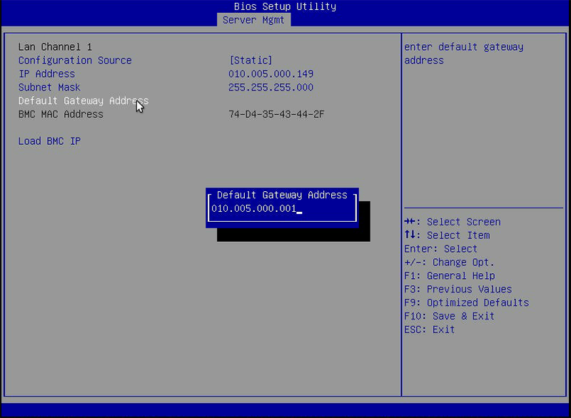
Fig. 2.1.6 Entering the Default Gateway Address
Save the changes, exit the BIOS, and allow the system to boot.
To connect to the TrueNAS® Storage Array’s out-of-band management port, enter the IP address into a web browser from a computer that is either within the same network or which is directly wired to the array. As shown in Figure 2.1.7, a login prompt appears.
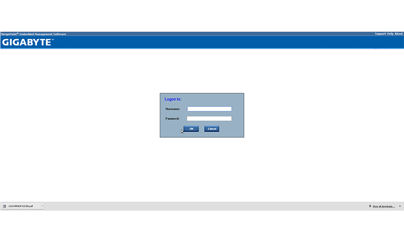
Fig. 2.1.7 Connecting to the IPMI Graphical Interface
Log in using the default Username of admin and the default Password of password.
The administrative password can be changed using the instructions in IPMI.
After logging in, click the vKVM and Media button at the top right to download the Java KVM Client. Run the client by clicking the Launch Java KVM Client button shown in Figure 2.1.8.
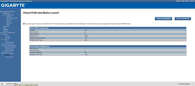
Fig. 2.1.8 Launching the Java KVM Client
When prompted for a program to open the file with, select the Java Web Start Launcher shown in Figure 2.1.9.
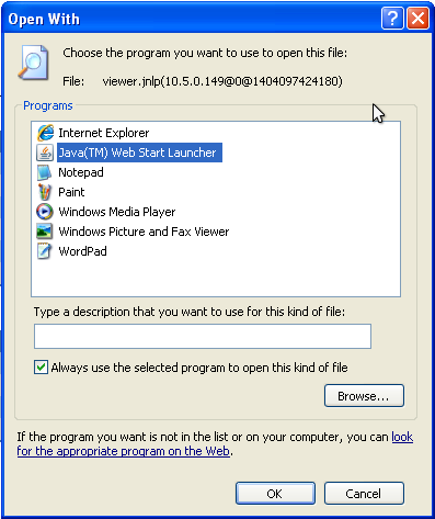
Fig. 2.1.9 Configure the Launch Program
If asked to verify running a program from an unknown publisher, check the box indicating that you understand the risks and press Run. An example is shown in Figure 2.1.10.
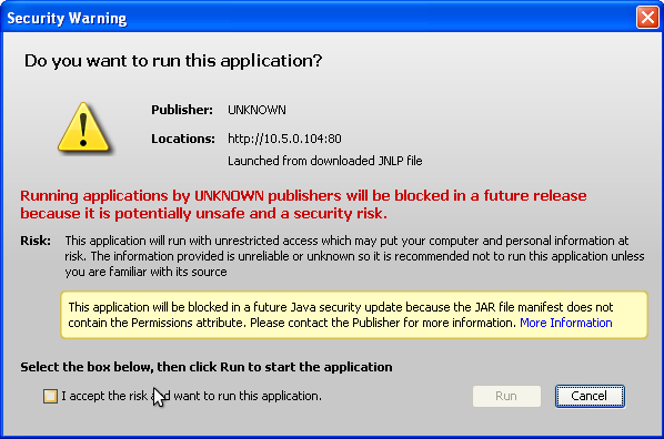
Fig. 2.1.10 Respond to Warning
When prompted that the connection is untrusted, as shown in Figure 2.1.11, press Continue.
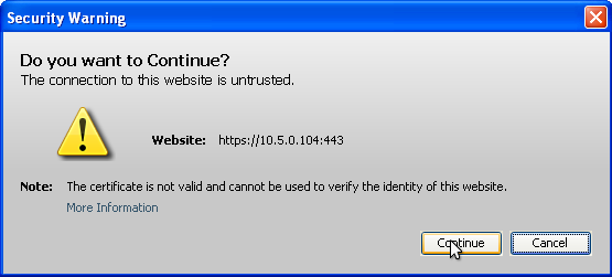
Fig. 2.1.11 Continue Through this Screen
With the out-of-band console open, the TrueNAS® Storage Array can be controlled as if using a directly-connected keyboard and monitor.
2.2. Console Setup Menu
The Console Setup menu, shown in Figure 2.2.1, appears at the end of the boot process. If the TrueNAS® system has a keyboard and monitor, this Console Setup menu can be used to administer the system.
Note
When connecting to the TrueNAS® system with SSH or the web
Shell, the Console Setup menu is not shown by default.
It can be started by the root user or another user with root
permissions by typing /etc/netcli.
The Console Setup menu can be disabled by unchecking Enable Console Menu in .
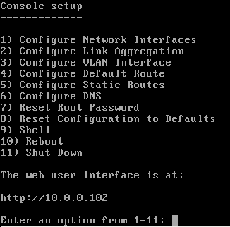
Fig. 2.2.1 Console Setup Menu
The menu provides these options:
1) Configure Network Interfaces provides a configuration wizard to set up the system’s network interfaces. If the system has been licensed for High Availability (HA), the wizard prompts for IP addresses for both (This Node) and (Node B).
The wizard also prompts marking an interface as critical for failover. This allows logging in to the web interface available at the virtual IP address after a failover.
2) Configure Link Aggregation is for creating or deleting link aggregations.
3) Configure VLAN Interface is used to create or delete VLAN interfaces.
4) Configure Default Route is used to set the IPv4 or IPv6 default gateway. When prompted, enter the IP address of the default gateway.
5) Configure Static Routes prompts for the destination network and gateway IP address. Re-enter this option for each static route needed.
6) Configure DNS prompts for the name of the DNS domain and
the IP address of the first DNS server. When adding multiple DNS servers,
press Enter to enter the next one. Press Enter twice to
leave this option.
7) Reset Root Password is used to reset a lost or forgotten
root password. Select this option and follow the prompts to
set the password.
8) Reset Configuration to Defaults Caution! This option deletes all of the configuration settings made in the administrative GUI and is used to reset a TrueNAS® system back to defaults. Before selecting this option, make a full backup of all data and make sure all encryption keys and passphrases are known! After this option is selected, the configuration is reset to defaults and the system reboots. can be used to re-import pools.
9) Shell starts a shell for running FreeBSD commands. To leave the shell, type exit.
10) Reboot reboots the system.
11) Shut Down shuts down the system.
Note
The numbering and quantity of options on this menu can change due to software updates, service agreements, or other factors. Please carefully check the menu before selecting an option, and keep this in mind when writing local procedures.
During boot, TrueNAS® automatically attempts to connect to a DHCP server from all live interfaces. If it successfully receives an IP address, the address is displayed so it can be used to access the graphical user interface. In the example seen in Figure 2.2.1, the TrueNAS® system is accessible at http://10.0.0.102.
Some TrueNAS® systems are set up without a monitor, making it challenging to determine which IP address has been assigned. On networks that support Multicast DNS (mDNS), the hostname and domain can be entered into the address bar of a browser. By default, this value is truenas.local.
If the TrueNAS® server is not connected to a network with a DHCP server, use the console network configuration menu to manually configure the interface as shown here. In this example, the TrueNAS® system has one network interface, em0.
Enter an option from 1-12: 1
1) em0
Select an interface (q to quit): 1
Reset network configuration (y/n) n
Configure interface for DHCP? (y/n) n
Configure IPv4? (y/n) y
Interface name:     (press enter, the name can be blank)
Several input formats are supported
Example 1 CIDR Notation:
    192.168.1.1/24
Example 2 IP and Netmask separate:
    IP: 192.168.1.1
    Netmask: 255.255.255.0, or /24 or 24
IPv4 Address: 192.168.1.108/24
Saving interface configuration: Ok
Configure IPv6? (y/n) n
Restarting network: ok

...

The web user interface is at
http://192.168.1.108
2.3. Accessing the Administrative GUI
After the system has an IP address, enter that address into a graphical web browser from a computer on the same network as the TrueNAS® system. A prompt appears to enter the password for the root user, as shown in Figure 2.3.1.
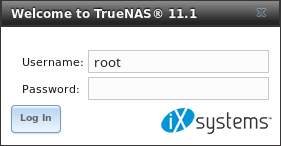
Fig. 2.3.1 Enter the Root Password
Enter the default password of abcd1234.
Note
The default root password can be changed to a more secure value by going to . Highlight the entry for root, click the Modify User button, enter the new password in the Password and Password confirmation fields, and click OK to save the new password to use on subsequent logins.
On the first login, the End User License Agreement (EULA) found in Appendix A: TrueNAS Software End User License Agreement is displayed. To accept the EULA, click I agree.
Next, a box for the license key is displayed. Paste in the license key to access the web interface.
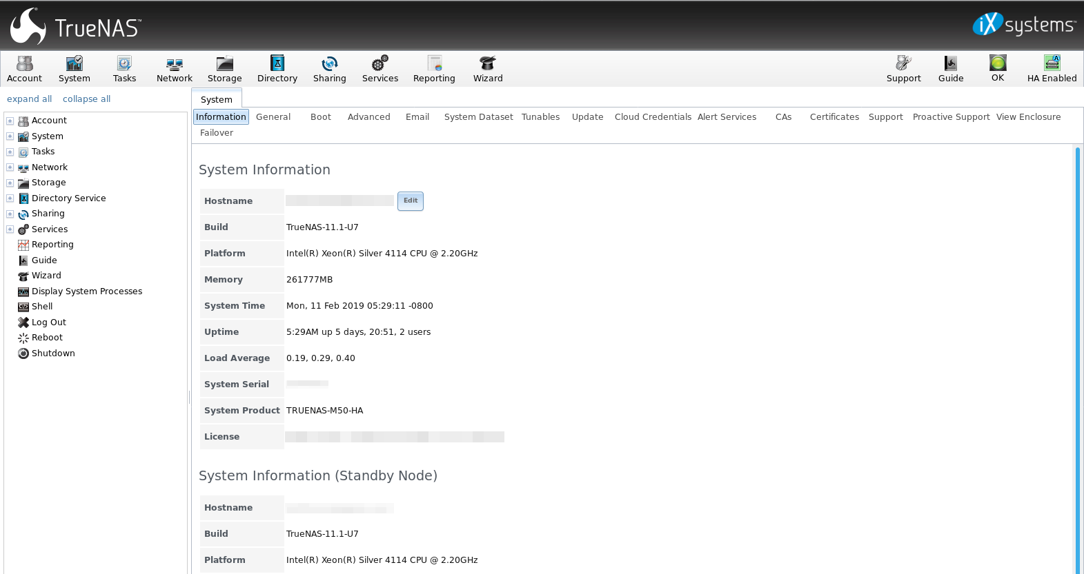
Fig. 2.3.2 TrueNAS® Graphical Configuration Menu
Note
Entering the license key for a High Availability pair is not allowed unless both the active and standby computers are up. The key is entered on the active computer.
Note
If the storage devices have been encrypted, a prompt appears for the passphrase. It must be correctly entered for the data on the disks to be accessible. If the system has also been licensed for High Availability (HA), the passphrase will be remembered as long as either node in the HA unit remains up. If both nodes are powered off, the passphrase must be re-entered when the first node powers back up.
If the user interface is not accessible by IP address from a browser, check these things:
- Are proxy settings enabled in the browser configuration? If so, disable the settings and try connecting again.
- If the page does not load, make sure that a ping reaches the TrueNAS® system’s IP address. If the address is in a private IP address range, it is only accessible from within that private network.
- If the user interface loads but is unresponsive or seems to be missing menu items, try a different web browser. IE9 has known issues and will not display the graphical administrative interface correctly if compatibility mode is turned on. If the GUI cannot be accessed with Internet Explorer, use Firefox instead.
- If “An error occurred!” messages are shown when attempting to configure an item in the GUI, make sure that the browser is set to allow cookies from the TrueNAS® system.
This blog post describes some applications which can be used to access the TrueNAS® system from an iPad or iPhone.
The rest of this Guide describes all of the configuration screens available within the TrueNAS® graphical administrative interface. The screens are listed in the order that they appear within the tree, or the left frame of the graphical interface.
Note
iXsystems recommends that you contact your iXsystems Support Representative for initial setup and configuration assistance.
Once the system has been configured and you are familiar with the configuration workflow, the rest of this document can be used as a reference guide to the features built into the TrueNAS® Storage Array.
Note
It is important to use the graphical interface (or the console setup menu) for all non-ZFS configuration changes. TrueNAS® uses a configuration database to store its settings. If changes are made at the command line, they will not be written to the configuration database. This means that these changes will not persist after a reboot and will be overwritten by the values in the configuration database during an upgrade.