9. Sharing
Shares are created to make part or all of a volume accessible to other computers on the network. The type of share to create depends on factors like which operating systems are being used by computers on the network, security requirements, and expectations for network transfer speeds.
TrueNAS® provides a Wizard for creating shares. The Wizard automatically creates the correct type of dataset and permissions for the type of share, sets the default permissions for the share type, and starts the service needed by the share. It is recommended to use the Wizard to create shares, fine-tune the share settings using the instructions in the rest of this chapter if needed, then fine-tune the default permissions from the client operating system to meet the requirements of the network.
Note
Shares are created to provide and control access to an area of storage. Before creating shares, making a list of the users that need access to storage data, which operating systems these users are using, whether all users should have the same permissions to the stored data, and whether these users should authenticate before accessing the data is recommended. This information can help determine which type of shares are needed, whether multiple datasets are needed to divide the storage into areas with different access and permissions, and how complex it will be to set up those permission requirements. Note that shares are used to provide access to data. When a share is deleted, it removes access to data but does not delete the data itself.
These types of shares and services are available:
- AFP: Apple Filing Protocol shares are used when the client computers all run macOS. Apple has deprecated AFP in favor of SMB. Using AFP in modern networks is no longer recommended.
- Unix (NFS): Network File System shares are accessible from macOS, Linux, BSD, and the professional and enterprise versions (but not the home editions) of Windows. This can be a good choice when the client computers do not all run the same operating system but NFS client software is available for all of them.
- WebDAV: WebDAV shares are accessible using an authenticated web browser (read-only) or WebDAV client running on any operating system.
- SMB: Server Message Block shares, also known as Common Internet File System (CIFS) shares, are accessible by Windows, macOS, Linux, and BSD computers. Access is slower than an NFS share due to the single-threaded design of Samba. SMB provides more configuration options than NFS and is a good choice on a network for Windows or Mac systems. However, it is a poor choice if the CPU on the TrueNAS® system is limited. If it is maxed out, upgrade the CPU or consider a different type of share.
- Block (iSCSI): block or iSCSI shares appear as an unformatted disk to clients running iSCSI initiator software or a virtualization solution such as VMware. These are usually used as virtual drives.
Fast access from any operating system can be obtained by configuring the FTP service instead of a share and using a cross-platform FTP file manager application such as Filezilla. Secure FTP can be configured if the data needs to be encrypted.
When data security is a concern and the network users are familiar with SSH command line utilities or WinSCP, consider using the SSH service instead of a share. It is slower than unencrypted FTP due to the encryption overhead, but the data passing through the network is encrypted.
Note
It is generally a mistake to share a volume or dataset with more than one share type or access method. Different types of shares and services use different file locking methods. For example, if the same volume is configured to use both NFS and FTP, NFS will lock a file for editing by an NFS user, but an FTP user can simultaneously edit or delete that file. This results in lost edits and confused users. Another example: if a volume is configured for both AFP and SMB, Windows users can be confused by the “extra” filenames used by Mac files and delete them. This corrupts the files on the AFP share. Pick the one type of share or service that makes the most sense for the types of clients accessing that volume, and use that single type of share or service. To support multiple types of shares, divide the volume into datasets and use one dataset per share.
This section demonstrates configuration and fine-tuning of AFP, NFS, SMB, WebDAV, and iSCSI shares. FTP and SSH configurations are described in Services.
9.1. Apple (AFP) Shares
TrueNAS® uses the Netatalk AFP server to share data with Apple systems. This section describes the configuration screen for fine-tuning AFP shares created using the Wizard. It then provides configuration examples for using the Wizard to create a guest share, configuring Time Machine to back up to a dataset on the TrueNAS® system, and for connecting to the share from a macOS client.
To view the AFP share created by the Wizard, click and highlight the name of the share. Click its Edit button to see the configuration options shown in Figure 9.1.1. The values showing for these options will vary, depending upon the information given when the share was created.
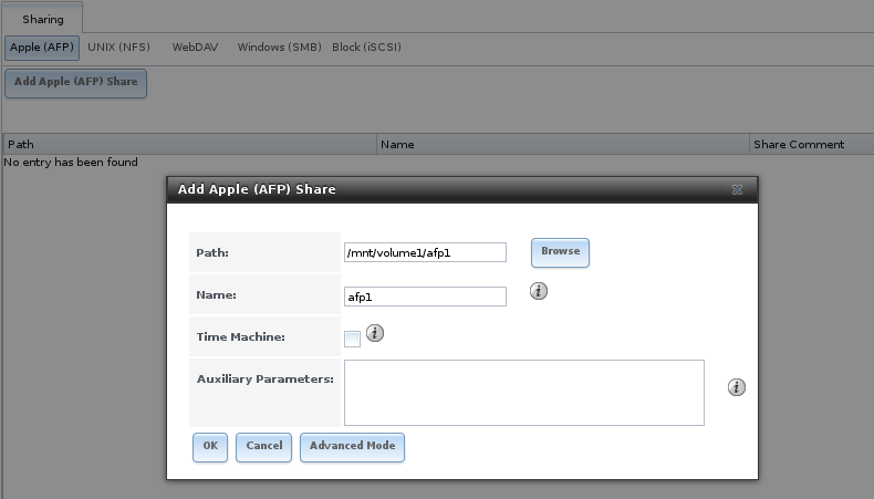
Fig. 9.1.1 Creating an AFP Share
Note
Table 9.1.1 summarizes the options available to fine-tune an AFP share. Leaving these options at the default settings is recommended as changing them can cause unexpected behavior. Most settings are only available with Advanced Mode. Do not change an advanced option without fully understanding the function of that option. Refer to Setting up Netatalk for a more detailed explanation of these options.
| Setting | Value | Advanced Mode | Description |
|---|---|---|---|
| Path | browse button | Browse to the volume/dataset to share. Do not nest additional volumes, datasets, or symbolic links beneath this path. Netatalk does not fully support nesting functionality. | |
| Name | string | Enter the volume name that appears in in macOS after selecting in the Finder menu. Limited to 27 characters and cannot contain a period. | |
| Share Comment | string | ✓ | Enter an optional comment. |
| Allow List | string | ✓ | Comma-delimited list of allowed users and/or groups where groupname begins with a @.
Note that adding an entry will deny any user/group that is not specified. |
| Deny List | string | ✓ | Comma-delimited list of denied users and/or groups where groupname begins with a @.
Note that adding an entry will allow all users/groups that are not specified. |
| Read-only Access | string | ✓ | Comma-delimited list of users and/or groups who only have read access where groupname
begins with a @. |
| Read-write Access | string | ✓ | Comma-delimited list of users and/or groups who have read and write access where groupname
begins with a @. |
| Time Machine | checkbox | Set to advertise TrueNAS® as a Time Machine disk so it can be found by Macs. Setting multiple shares for Time Machine use is not recommended. When multiple Macs share the same pool, low diskspace issues and intermittently failed backups can occur. | |
| Zero Device Numbers | checkbox | ✓ | Enable when the device number is not constant across a reboot. |
| No Stat | checkbox | ✓ | If enabled, AFP does not stat the volume path when enumerating the volumes list. Useful for automounting or volumes created by a preexec script. |
| AFP3 UNIX Privs | checkbox | ✓ | Set to enable Unix privileges supported by Mac OS X 10.5 and higher. Do not enable if the network has Mac OS X 10.4 or lower clients. Those systems do not support this feature. |
| Default file permission | checkboxes | ✓ | Only works with Unix ACLs. New files created on the share are set with the selected permissions. |
| Default directory permission | checkboxes | ✓ | Only works with Unix ACLs. New directories created on the share are set with the selected permissions. |
| Default umask | integer | ✓ | Umask is used for newly created files. Default is 000 (anyone can read, write, and execute). |
| Hosts Allow | string | ✓ | Enter a list of allowed hostnames or IP addresses. Separate entries with a comma, space, or tab. |
| Hosts Deny | string | ✓ | Enter a list of denied hostnames or IP addresses. Separate entries with a comma, space, or tab. |
| Auxiliary Parameters | string | Additional afp.conf parameters not covered by other option fields. |
9.1.1. Creating AFP Guest Shares
AFP supports guest logins, meaning that macOS users can access the AFP share without requiring their user accounts to first be created on or imported into the TrueNAS® system.
Note
When a guest share is created along with a share that requires authentication, AFP only maps users who log in as guest to the guest share. If a user logs in to the share that requires authentication, permissions on the guest share can prevent that user from writing to the guest share. The only way to allow both guest and authenticated users to write to a guest share is to set the permissions on the guest share to 777 or to add the authenticated users to a guest group and set the permissions to 77x.
Before creating a guest share, go to and make sure that the Guest Access option is enabled.
To create the AFP guest share, click Wizard, then click the Next button twice to display the screen shown in Figure 9.1.2. Complete these fields in this screen:
- Share name: enter a name for the share that is identifiable but less than 27 characters long. This name cannot contain a period. In this example, the share is named afp_guest.
- Click the button for Mac OS X (AFP).
- Click the Ownership button. Click the drop-down User menu and select nobody. Click the Return button to return to the previous screen.
- Click the Add button. The share is not created until the button is clicked. Clicking the Add button adds an entry to the Name frame with the name that was entered in Share name.

Fig. 9.1.2 Creating a Guest AFP Share
Click the Next button twice, then the Confirm button to create the share. The Wizard automatically creates a dataset for the share that contains the correct default permissions and starts the AFP service so the share is immediately available. The new share is also added as an entry to .
macOS users can use Finder to connect to the guest AFP share by
clicking
.
In the example shown in Figure 9.1.3,
the user entered afp:// followed by the IP address of the
TrueNAS® system.
Click the Connect button. Once connected, Finder opens automatically. The name of the AFP share is displayed in the SHARED section in the left frame and the contents of any data saved in the share is displayed in the right frame.
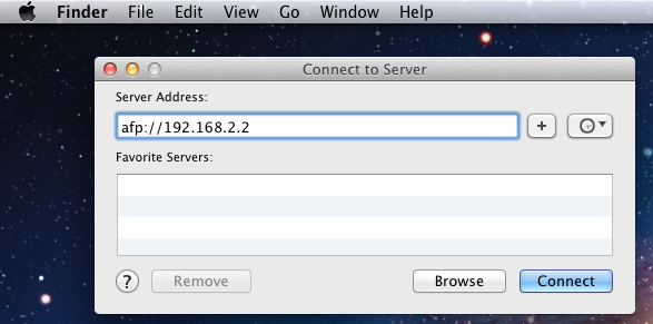
Fig. 9.1.3 Connect to Server Dialogue
To disconnect from the volume, click the eject button in the Shared sidebar.
9.2. Unix (NFS) Shares
TrueNAS® supports sharing pools, datasets, and directories over the Network File System (NFS). Clients use the mount command to mount the share. Mounted NFS shares appear as another directory on the client system. Some Linux distros require the installation of additional software to mount an NFS share. Windows systems must enable Services for NFS in the Ultimate or Enterprise editions or install an NFS client application.
To create an NFS share using the Wizard, click the Next button three times to display the screen shown in Figure 9.2.1. Enter a Share name. Spaces are not allowed in these names. Click the button for Generic Unix (NFS), then click Add so the share name appears in the Name frame. When finished, click the Next button twice, then the Confirm button to create the share. Creating an NFS share using the wizard automatically creates a new dataset for the share, starts the services required for NFS, and adds an entry in . Depending on the requirements, the IP addresses that are allowed to access the NFS share can be restricted, or the permissions adjusted.
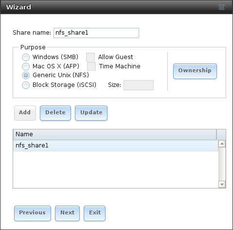
Fig. 9.2.1 NFS Share Wizard
NFS shares are edited by clicking , highlighting the entry for the share, and clicking the Edit button. In the example shown in Figure 9.2.2, the configuration screen is open for the nfs_share1 share.
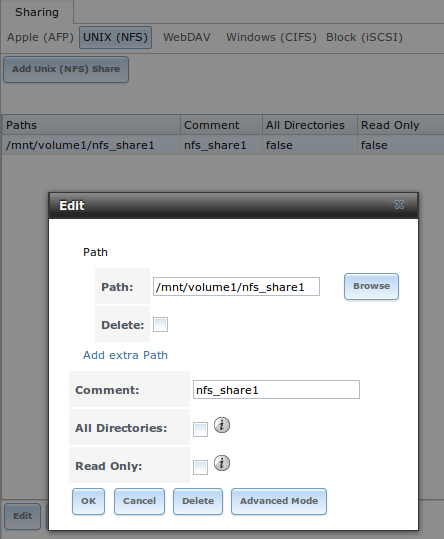
Fig. 9.2.2 NFS Share Settings
Remember these points when creating NFS shares:
- Clients specify the Path when mounting the share.
- The Maproot and Mapall options cannot both be enabled. The Mapall options supersede the Maproot options. To restrict only the root user permissions, set the Maproot option. To restrict permissions of all users, set the Mapall options.
- Each volume or dataset is considered to be a unique filesystem. Individual NFS shares cannot cross filesystem boundaries. Adding paths to share more directories only works if those directories are within the same filesystem.
- The network and host must be unique to both each created share and
the filesystem or directory included in that share. Because
/etc/exportsis not an access control list (ACL), the rules contained in/etc/exportsbecome undefined with overlapping networks or when using the same share with multiple hosts. - The All dirs option can only be used once per share per filesystem.
To better understand these restrictions, consider a scenario where there are:
- two networks, 10.0.0.0/8 and 20.0.0.0/8
- a ZFS volume named
volume1with 2 datasets nameddataset1anddataset2 dataset1contains directories nameddirectory1,directory2, anddirectory3
Because of restriction #3, an error is shown when trying to create one NFS share like this:
- Authorized networks set to 10.0.0.0/8 20.0.0.0/8
- Path set to
/mnt/volume1/dataset1and/mnt/volume1/dataset1/directory1
The correct method to configure this share is to set the
Path to /mnt/volume1/dataset1 and set
All Directories. This allows the client to also mount
/mnt/volume1/dataset1/directory1 when
/mnt/volume1/dataset1 is mounted.
Additional paths are used to define specific directories to be shared.
For example, dataset1 has three directories. To share only
/mnt/volume1/dataset1/directory1 and
/mnt/volume1/dataset1/directory2, create paths for
directory1 and directory2 within the share.
This excludes directory3 from the share.
Restricting a specific directory to a single network is done by creating a share for the volume or dataset and a share for the directory within that volume or dataset. Define the authorized networks for both shares.
First NFS share:
- Authorized networks set to 10.0.0.0/8
- Path set to
/mnt/volume1/dataset1
Second NFS share:
- Authorized networks set to 20.0.0.0/8
- Path set to
/mnt/volume1/dataset1/directory1
Note that this requires creating two shares. It cannot be done with only one share.
Table 9.2.1 summarizes the available configuration options in NFS Share Settings. Click Advanced Mode to see all settings.
| Setting | Value | Advanced Mode | Description |
|---|---|---|---|
| Path | browse button | Browse to the volume, dataset, or directory to be shared. Click Add extra Path to add multiple directories to this share. | |
| Comment | string | Text describing the share. Typically used to name the share. If left empty, this shows the Path entries of the share. | |
| Authorized networks | string | ✓ | Space-delimited list of allowed networks in network/mask CIDR notation. Example: 1.2.3.0/24. Leave empty to allow all. |
| Authorized IP addresses or hosts | string | ✓ | Space-delimited list of allowed IP addresses or hostnames. Leave empty to allow all. |
| All directories | checkbox | Allow the client to also mount any subdirectories of the selected pool or dataset. | |
| Read only | checkbox | Prohibit writing to the share. | |
| Quiet | checkbox | ✓ | Restrict some syslog diagnostics to avoid some error messages. See exports(5) for examples. |
| Maproot User | drop-down menu | ✓ | When a user is selected, the root user is limited to permissions of that user. |
| Maproot Group | drop-down menu | ✓ | When a group is selected, the root user is also limited to permissions of that group. |
| Mapall User | drop-down menu | ✓ | All clients use the permissions of the specified user. |
| Mapall Group | drop-down menu | ✓ | All clients use the permissions of the specified group. |
| Security | selection | ✓ | Only appears if Enable NFSv4 is enabled in . Choices are sys or these Kerberos options: krb5 (authentication only), krb5i (authentication and integrity), or krb5p (authentication and privacy). If multiple security mechanisms are added to the Selected column using the arrows, use the Up or Down buttons to list in order of preference. |
9.2.1. Example Configuration
By default, the Mapall fields are not set. This means that when a user connects to the NFS share, the user has the permissions associated with their user account. This is a security risk if a user is able to connect as root as they will have complete access to the share.
A better option is to do this:
- Specify the built-in nobody account to be used for NFS access.
- In the Change Permissions screen of the volume/dataset that is being shared, change the owner and group to nobody and set the permissions according to the desired requirements.
- Select nobody in the Mapall User and Mapall Group drop-down menus for the share in .
With this configuration, it does not matter which user account connects to the NFS share, as it will be mapped to the nobody user account and will only have the permissions that were specified on the volume/dataset. For example, even if the root user is able to connect, it will not gain root access to the share.
9.2.2. Connecting to the Share
The following examples share this configuration:
- The TrueNAS® system is at IP address 192.168.2.2.
- A dataset named
/mnt/volume1/nfs_share1is created and the permissions set to the nobody user account and the nobody group. - An NFS share is created with these attributes:
- Path:
/mnt/volume1/nfs_share1 - Authorized Networks: 192.168.2.0/24
- All Directories option is enabled
- MapAll User is set to nobody
- MapAll Group is set to nobody
- Path:
9.2.2.1. From BSD or Linux
NFS shares are mounted on BSD or Linux clients with this command executed as the superuser (root) or with sudo:
mount -t nfs 192.168.2.2:/mnt/volume1/nfs_share1 /mnt
- -t nfs specifies the filesystem type of the share
- 192.168.2.2 is the IP address of the TrueNAS® system
- /mnt/volume/nfs_share1 is the name of the directory to be shared, a dataset in this case
- /mnt is the mountpoint on the client system. This must be an existing, empty directory. The data in the NFS share appears in this directory on the client computer.
Successfully mounting the share returns to the command prompt without any status or error messages.
Note
If this command fails on a Linux system, make sure that the nfs-utils package is installed.
This configuration allows users on the client system to copy files to
and from /mnt (the mount point). All files are owned by
nobody:nobody. Changes to any files or directories in /mnt
write to the TrueNAS® system /mnt/volume1/nfs_share1 dataset.
NFS share settings cannot be changed when the share is mounted on a client computer. The umount command is used to unmount the share on BSD and Linux clients. Run it as the superuser or with sudo on each client computer:
umount /mnt
9.2.2.2. From Microsoft
Windows NFS client support varies with versions and releases. For best results, use Windows (SMB) Shares.
9.2.2.3. From macOS
A macOS client uses Finder to mount the NFS volume. Go to . In the Server Address field, enter nfs:// followed by the IP address of the TrueNAS® system and the name of the volume/dataset being shared by NFS. The example shown in Figure 9.2.3 continues with our example of 192.168.2.2:/mnt/volume1/nfs_share1.
Finder opens automatically after connecting. The IP address of the
TrueNAS® system displays in the SHARED section in the left frame and the
contents of the share display in the right frame.
Figure 9.2.4 shows an example where
/mnt/data has one folder named images. The user can now
copy files to and from the share.
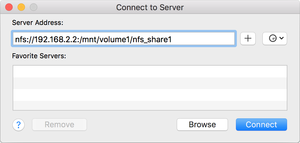
Fig. 9.2.3 Mounting the NFS Share from macOS
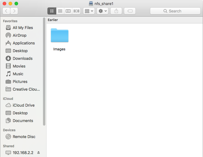
Fig. 9.2.4 Viewing the NFS Share in Finder
9.2.3. Troubleshooting NFS
Some NFS clients do not support the NLM (Network Lock Manager) protocol used by NFS. This is the case if the client receives an error that all or part of the file may be locked when a file transfer is attempted. To resolve this error, add the option -o nolock when running the mount command on the client to allow write access to the NFS share.
If a “time out giving up” error is shown when trying to mount the share from a Linux system, make sure that the portmapper service is running on the Linux client. If portmapper is running and timeouts are still shown, force the use of TCP by including -o tcp in the mount command.
If a RPC: Program not registered error is shown, upgrade to
the latest version of TrueNAS® and restart the NFS service after the
upgrade to clear the NFS cache.
If clients see “reverse DNS” errors, add the TrueNAS® IP address in the Host name data base field of .
If clients receive timeout errors when trying to mount the share, add the client IP address and hostname to the Host name data base field in .
Some older versions of NFS clients default to UDP instead of TCP and do not auto-negotiate for TCP. By default, TrueNAS® uses TCP. To support UDP connections, go to and enable the Serve UDP NFS clients option.
The nfsstat -c or nfsstat -s commands can be helpful
to detect problems from the Shell. A high proportion of retries
and timeouts compared to reads usually indicates network problems.
9.3. WebDAV Shares
In TrueNAS®, WebDAV shares can be created so that authenticated users can browse the contents of the specified volume, dataset, or directory from a web browser.
Configuring WebDAV shares is a two step process. First, create the WebDAV shares to specify which data can be accessed. Then, configure the WebDAV service by specifying the port, authentication type, and authentication password. Once the configuration is complete, the share can be accessed using a URL in the format:
protocol://IP_address:port_number/share_name
where:
- protocol: is either http or https, depending upon the Protocol configured in .
- IP address: is the IP address or hostname of the TrueNAS® system. Take care when configuring a public IP address to ensure that the network firewall only allows access to authorized systems.
- port_number: is configured in . If the TrueNAS® system is to be accessed using a public IP address, consider changing the default port number and ensure that the network’s firewall only allows access to authorized systems.
- share_name: is configured in .
Entering the URL in a web browser brings up an authentication pop-up message. Enter a username of webdav and the password configured in .
Warning
At this time, only the webdav user is supported. For this reason, it is important to set a good password for this account and to only give the password to users which should have access to the WebDAV share.
To create a WebDAV share, click which will open the screen shown in Figure 9.3.1.
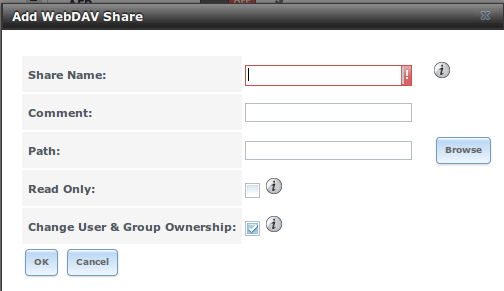
Fig. 9.3.1 Adding a WebDAV Share
Table 9.3.1 summarizes the available options.
| Setting | Value | Description |
|---|---|---|
| Share Path Name | string | Enter a name for the share. |
| Comment | string | Optional. |
| Path | browse button | Browse to the volume/dataset to share. |
| Read Only | checkbox | Set to prohibit users from writing to the share. |
| Change User & Group Ownership | checkbox | Enable to automatically set the share contents to the webdav user and group. |
After clicking OK, a pop-up asks about enabling the service. Once the service starts, review the settings in as they are used to determine which URL is used to access the WebDAV share and whether or not authentication is required to access the share. These settings are described in WebDAV.
9.4. Windows (SMB) Shares
TrueNAS® uses Samba to share volumes using Microsoft’s SMB protocol. SMB is built into the Windows and macOS operating systems and most Linux and BSD systems pre-install the Samba client in order to provide support for SMB. If the distro did not, install the Samba client using the distro software repository.
The SMB protocol supports many different types of configuration scenarios, ranging from the simple to complex. The complexity of the scenario depends upon the types and versions of the client operating systems that will connect to the share, whether the network has a Windows server, and whether Active Directory is being used. Depending on the authentication requirements, it might be necessary to create or import users and groups.
Samba supports server-side copy of files on the same share with clients from Windows 8 and higher. Copying between two different shares is not server-side. Windows 7 clients support server-side copying with Robocopy.
This chapter starts by summarizing the available configuration options. It demonstrates some common configuration scenarios as well as offering some troubleshooting tips. Reading through this entire chapter before creating any SMB shares is recommended to gain a better understanding of the configuration scenario that meets the specific network requirements.
SMB Tips and Tricks shows helpful hints for configuring and managing SMB networking. The FreeNAS and Samba (CIFS) permissions and Advanced Samba (CIFS) permissions on FreeNAS videos clarify setting up permissions on SMB shares. Another helpful reference is Methods For Fine-Tuning Samba Permissions.
Warning
SMB1 is disabled by default for security. If necessary, SMB1 can be enabled in .
Figure 9.4.1 shows the configuration screen that appears after clicking .
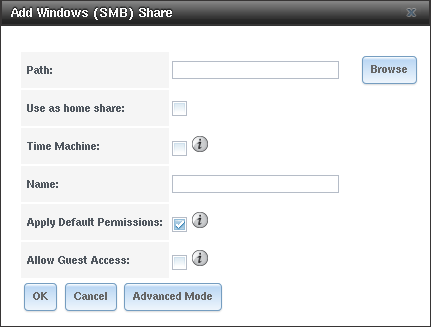
Fig. 9.4.1 Adding an SMB Share
Table 9.4.1 summarizes the options when creating a SMB share. Some settings are only available after clicking the Advanced Mode button. For simple sharing scenarios, Advanced Mode options are not needed. For more complex sharing scenarios, only change an Advanced Mode option after fully understanding the function of that option. smb.conf(5) provides more details for each configurable option.
| Setting | Value | Advanced Mode | Description |
|---|---|---|---|
| Path | browse button | Select the volume, dataset, or directory to share. | |
| Use as home share | checkbox | Set to allow this share to hold user home directories. Only one share can be the home share. Note that lower case names for user home directories
are strongly recommended, as Samba maps usernames to all lower case. For example, the username John will be mapped to a home directory named
john. If the Path to the home share includes an upper case username, delete the existing user and recreate it
in with an all lower case Username. Return to to create the home
share, and select the Path that contains the new lower case username. |
|
| Time Machine | checkbox | Enable Time Machine backups for this share. See Configuring Time Machine Backups. | |
| Name | string | Name the new share. | |
| Comment | string | ✓ | Optional description. |
| Apply Default Permissions | checkbox | ACLs grant read and write for owner or group and read-only for others. Leave this unset when creating shares on a system with custom ACLs. | |
| Export Read Only | checkbox | ✓ | Prohibit write access to the share. |
| Browsable to Network Clients | checkbox | ✓ | Users see the contents of /home. This includes other home directories of other users. Unset for users to only see their own home
directory. |
| Export Recycle Bin | checkbox | ✓ | Set for deleted files to move to a .recycle in the root folder of the share. The .recycle directory can be deleted to reclaim
space and is recreated whenever a file is deleted. |
| Show Hidden Files | checkbox | ✓ | Disable the Windows hidden attribute on a new Unix hidden file. Unix hidden filenames start with a dot: .foo. Existing files are not
affected. |
| Allow Guest Access | checkbox | Allow access to this share without a password. See the SMB service for more information about guest user permissions. | |
| Only Allow Guest Access | checkbox | ✓ | Requires Allow guest access to also be enabled. Forces guest access for all connections. |
| Access Based Share Enumeration | checkbox | ✓ | When enabled, users can only see the shares they have permission to access. To change the default that grants everyone access, use the computer management MMC on Windows or the sharesec command-line utility. |
| Hosts Allow | string | ✓ | Enter a list of allowed hostnames or IP addresses. Separate entries with a comma (,), space, or tab. |
| Hosts Deny | string | ✓ | Enter a list of denied hostnames or IP addresses. Separate entries with a comma (,), space, or tab. Specify ALL and list
any hosts from Hosts Allow to have those hosts take precedence. |
| VFS Objects | selection | ✓ | Add virtual file system modules to enhance functionality. Table 9.4.2 summarizes the available modules. |
| Periodic Snapshot Task | drop-down menu | ✓ | Used to configure directory shadow copies on a per-share basis. Select the pre-configured periodic snapshot task to use for the shadow copies of the share. Periodic snapshots must be recursive. |
| Auxiliary Parameters | string | ✓ | Additional smb4.conf parameters not covered by other option fields. |
Here are some notes about ADVANCED MODE settings:
- Hostname lookups add some time to accessing the SMB share. If only using IP addresses, unset the Hostnames lookups option in .
- When the Browsable to Network Clients option is enabled (the default), the share is visible through Windows File Explorer or through net view. When the Use as a home share option is selected, deselecting the Browsable to Network Clients option hides the share named homes so that only the dynamically generated share containing the authenticated user home directory will be visible. By default, the homes share and the user home directory are both visible. Users are not automatically granted read or write permissions on browsable shares. This option provides no real security because shares that are not visible in Windows File Explorer can still be accessed with a UNC path.
- If some files on a shared volume should be hidden and inaccessible to users, put a veto files= line in the Auxiliary Parameters field. The syntax for the veto files option and some examples can be found in the smb.conf manual page.
Samba disables NTLMv1 authentication by default for security. Standard configurations of Windows XP and some configurations of later clients like Windows 7 will not be able to connect with NTLMv1 disabled. Security guidance for NTLMv1 and LM network authentication has information about the security implications and ways to enable NTLMv2 on those clients. If changing the client configuration is not possible, NTLMv1 authentication can be enabled by enabling the NTLMv1 auth option in .
Table 9.4.2 provides an overview of the available VFS modules. Be sure to research each module before adding or deleting it from the Selected column of the VFS Objects field of the share. Some modules need additional configuration after they are added. Refer to Stackable VFS modules and the vfs_* man pages for more details.
| Value | Description |
|---|---|
| acl_tdb | Stores NTFS ACLs in a tdb file to enable full mapping of Windows ACLs. |
| acl_xattr | Stores NTFS ACLs in Extended Attributes (EAs) to enable the full mapping of Windows ACLs. |
| aio_fork | Enables async I/O. |
| audit | Logs share access, connects/disconnects, directory opens/creates/removes, and file opens/closes/renames/unlinks/chmods to syslog. |
| cacheprime | Primes the kernel file data cache. |
| cap | Translates filenames to and from the CAP encoding format, commonly used in Japanese language environments. |
| catia | Improves Mac interoperability by translating characters that are unsupported by Windows. |
| commit | Tracks the amount of data written to a file and synchronizes it to disk when a specified amount accumulates. |
| crossrename | Allows server side rename operations even if source and target are on different physical devices. |
| default_quota | Stores the default quotas that are reported to a windows client in the quota record of a user. |
| dfs_samba4 | Distributed file system for providing an alternative name space, load balancing, and automatic failover. |
| dirsort | Sorts directory entries alphabetically before sending them to the client. |
| expand_msdfs | Enables support for Microsoft Distributed File System (DFS). |
| extd_audit | Sends audit logs to both syslog and the Samba log files. |
| fake_acls | Stores file ownership and ACLs as extended attributes. |
| fake_perms | Allows roaming profile files and directories to be set as read-only. |
| fruit | Enhances macOS support by providing the SMB2 AAPL extension and Netatalk interoperability. Automatically loads catia and streams_xattr but read the caveat in NOTE below table. |
| full_audit | Record selected client operations to the system log. |
| ixnas | Experimental module to improve ACL compatibility with Windows and store DOS attributes as file flags. |
| linux_xfs_sgid | Used to work around an old Linux XFS bug. |
| media_harmony | Allows Avid editorial workstations to share a network drive. |
| netatalk | Eases the co-existence of SMB and AFP shares. |
| offline | Marks all files in the share with the DOS offline attribute. This can prevent Windows Explorer from reading files just to make thumbnail images. |
| posix_eadb | Provides Extended Attributes (EAs) support so they can be used on filesystems which do not provide native support for EAs. |
| preopen | Useful for video streaming applications that want to read one file per frame. |
| readahead | Useful for Windows Vista clients reading data using Windows Explorer. |
| readonly | Marks a share as read-only for all clients connecting within the configured time period. |
| shadow_copy | Allows Microsoft shadow copy clients to browse shadow copies on Windows shares. |
| shadow_copy_test | Shadow copy testing. |
| shell_snap | Provides shell-script callouts for snapshot creation and deletion operations issued by remote clients using the File Server Remote VSS Protocol (FSRVP). |
| skel_opaque | Implements dummy versions of all VFS modules (useful to VFS module developers). |
| skel_transparent | Implements dummy passthrough functions of all VFS modules (useful to VFS module developers). |
| snapper | Provides the ability for remote SMB clients to access shadow copies of FSRVP snapshots using Windows Explorer. |
| streams_depot | Experimental module to store alternate data streams in a central directory. The association with the primary file can be lost due to inode numbers changing when a directory is copied to a new location (see https://marc.info/?l=samba&m=132542069802160&w=2). |
| streams_xattr | Enabled by default. Enables storing of NTFS alternate data streams in the file system. |
| syncops | Ensures metadata operations are performed synchronously. |
| time_audit | Logs system calls that take longer than the number of defined milliseconds. |
| unityed_media | Allows multiple Avid clients to share a network drive. |
| winmsa | Emulate Microsoft’s MoveSecurityAttributes=0 registry option, setting the ACL for file and directory hierarchies to inherit from the parent directory into which they are moved. |
| worm | Controls the writability of files and folders depending on their change time and an adjustable grace period. |
| xattr_tdb | Stores Extended Attributes (EAs) in a tdb file so they can be used on filesystems which do not provide support for EAs. |
| zfs_space | Correctly calculates ZFS space used by the share, including space used by ZFS snapshots, quotas, and resevations. Enabled by default. |
| zfsacl | Provide ACL extensions for proper integration with ZFS. Enabled by default. |
Note
Be careful when using multiple SMB shares, some with and some without fruit. macOS clients negotiate SMB2 AAPL protocol extensions on the first connection to the server, so mixing shares with and without fruit will globally disable AAPL if the first connection occurs without fruit. To resolve this, all macOS clients need to disconnect from all SMB shares and the first reconnection to the server has to be to a fruit-enabled share.
These VFS objects do not appear in the selection box:
- recycle: moves deleted files to the recycle directory instead of deleting them. Controlled by Export Recycle Bin in the SMB share options.
- shadow_copy2: a more recent implementation of
shadow_copy with some additional features.
shadow_copy2 and the associated parameters are automatically added
to the
smb4.confwhen a Periodic Snapshot Task is selected.
To view all active SMB connections and users, enter smbstatus in the Shell.
9.4.1. Configuring Unauthenticated Access
SMB supports guest logins, meaning that users can access the SMB share without needing to provide a username or password. This type of share is convenient as it is easy to configure, easy to access, and does not require any users to be configured on the TrueNAS® system. This type of configuration is also the least secure as anyone on the network can access the contents of the share. Additionally, since all access is as the guest user, even if the user inputs a username or password, there is no way to differentiate which users accessed or modified the data on the share. This type of configuration is best suited for small networks where quick and easy access to the share is more important than the security of the data on the share.
Note
Windows 10, Windows Server 2016 version 1709, and Windows Server 2019 disable SMB2 guest access. Read the Microsoft security notice for details about security vulnerabilities with SMB2 guest access and instructions to re-enable guest logins on these Microsoft systems.
To configure an unauthenticated SMB share, click Wizard, then click the Next button twice to display the screen shown in Figure 9.4.2. Complete the following fields in this screen:
- Share name: enter a name for the share that is useful. In this example, the share is named smb_insecure.
- Click the button for Windows (SMB) and enable the Allow Guest option.
- Click the Ownership button. Click the drop-down User menu and select nobody. Click the Return button to return to the previous screen.
- Click the Add button. If this step is forgotten, the share will not be created. Clicking the Add button adds an entry to the Name frame with the name that was entered in Share name.
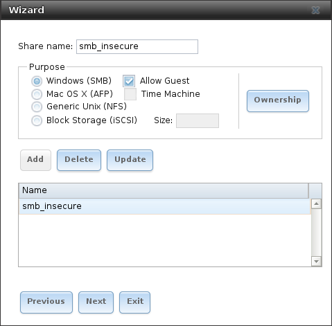
Fig. 9.4.2 Creating an Unauthenticated SMB Share
Click the Next button twice, then the Confirm button to create the share. The Wizard automatically creates a dataset for the share and starts the SMB service so the share is immediately available. The new share will appear in .
Users can now access the share from any SMB client and will not be prompted for their username or password. For example, to access the share from a Windows system, open Explorer and click on Network. For this configuration example, a system named FREENAS appears with a share named insecure_smb. The user can copy data to and from the unauthenticated SMB share.
9.4.2. Configuring Authenticated Access With Local Users
Most configuration scenarios require each user to have their own user account and to authenticate before accessing the share. This allows the administrator to control access to data, provide appropriate permissions to that data, and to determine who accesses and modifies stored data. A Windows domain controller is not needed for authenticated SMB shares, which means that additional licensing costs are not required. However, because there is no domain controller to provide authentication for the network, each user account must be created on the TrueNAS® system. This type of configuration scenario is often used in home and small networks as it does not scale well if many user accounts are needed.
Before configuring this scenario, determine which users need authenticated access. While not required for the configuration, it eases troubleshooting if the username and password that will be created on the TrueNAS® system matches that information on the client system. Next, determine if each user should have their own share to store their own data or if several users will be using the same share. The simpler configuration is to make one share per user as it does not require the creation of groups, adding the correct users to the groups, and ensuring that group permissions are set correctly.
To use the Wizard to create an authenticated SMB share, enter the following information, as shown in the example in Figure 9.4.3.
- Share name: enter a name for the share that is useful. In this example, the share is named smb_user1.
- Click the button for Windows (SMB).
- Click the Ownership button. To create the user account on the TrueNAS® system, type their name into the User field and enable the Create User option. The user’s password is then entered and confirmed. If the user will not be sharing this share with other users, type their name into the Group field and click Create Group. If, however, the share will be used by several users, instead type in a group name and enable the Create Group option. In the example shown in Figure 9.4.4, user1 has been used for both the user and group name, meaning that this share will only be used by user1. When finished, click Return to return to the screen shown in Figure 9.4.3.
- Click the Add button. If this step is forgotten, the share will not be created. Clicking the Add button adds an entry to the Name frame with the name that was entered in Share name.
When configuring multiple authenticated shares, repeat for each user, giving each user their own Share name and Ownership. When finished, click Next twice, then Confirm to create the shares. The Wizard automatically creates a dataset with the correct ownership for each share and starts the SMB service so the shares are available immediately. The new shares are also added to .

Fig. 9.4.3 Creating an Authenticated SMB Share
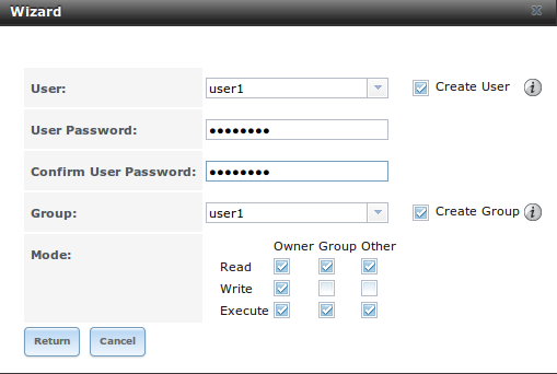
Fig. 9.4.4 Creating the User and Group
The authenticated share can now be tested from any SMB client. For example, to test an authenticated share from a Windows system, open Explorer and click on Network. For this configuration example, a system named FREENAS appears with a share named smb_user1. After clicking smb_user1, a Windows Security pop-up screen prompts for that user’s username and password. Enter the values that were configured for that share, in this case user user1. After authentication, the user can copy data to and from the SMB share.
To prevent Windows Explorer from hanging when accessing the share, map the share as a network drive. To do this, right-click the share and select Map network drive…. Choose a drive letter from the drop-down menu and click the Finish button.
Note that Windows systems cache a user’s credentials. This can cause
issues when testing or accessing multiple authenticated shares as only
one authentication is allowed at a time. When authenticating to a share,
if problems occur and the username and password are correct, type
cmd in the Search programs and files box and use
the following command to see if the share is already authenticated. In
this example, the user has already authenticated to the
smb_user1 share:
net use
New connections will be remembered.

Status         Local   Remote                  Network
------------------------------------------------------------------------
OK                     \\FREENAS\smb_user1 Microsoft Windows Network
The command completed successfully.
To clear the cache:
net use * /DELETE
You have these remote connections:
               \\FREENAS\smb_user1
Continuing will cancel the connections.

Do you want to continue this operation? <Y/N> [N]: y
An additional warning is shown if the share is currently open in Explorer:
There are open files and/or incomplete directory searches pending on the connection
to \\FREENAS|smb_user1.

Is it OK to continue disconnecting and force them closed? <Y/N> [N]: y
The command completed successfully.
The next time a share is accessed with Explorer, a prompt to authenticate will occur.
9.4.3. Configuring Shadow Copies
Shadow Copies, also known as the Volume Shadow Copy Service (VSS) or Previous Versions, is a Microsoft service for creating volume snapshots. Shadow copies can be used to restore previous versions of files from within Windows Explorer. Shadow Copy support is built into Vista and Windows 7. Windows XP or 2000 users need to install the Shadow Copy client.
When a periodic snapshot task is created on a ZFS volume that is configured as a SMB share in TrueNAS®, it is automatically configured to support shadow copies.
Before using shadow copies with TrueNAS®, be aware of the following caveats:
- If the Windows system is not fully patched to the latest service pack, Shadow Copies may not work. If no previous versions of files to restore are visible, use Windows Update to make sure that the system is fully up-to-date.
- Shadow copy support only works for ZFS pools or datasets. This means that the SMB share must be configured on a volume or dataset, not on a directory.
- Datasets are filesystems and shadow copies cannot traverse filesystems. To see the shadow copies in the child datasets, create separate shares for them.
- Shadow copies will not work with a manual snapshot. Creating a periodic snapshot task for the pool or dataset being shared by SMB or a recursive task for a parent dataset is recommended.
- The periodic snapshot task should be created and at least one snapshot should exist before creating the SMB share. If the SMB share was created first, restart the SMB service in .
- Appropriate permissions must be configured on the volume/dataset being shared by SMB.
- Users cannot delete shadow copies on the Windows system due to the way Samba works. Instead, the administrator can remove snapshots from the TrueNAS® administrative GUI. The only way to disable shadow copies completely is to remove the periodic snapshot task and delete all snapshots associated with the SMB share.
To configure shadow copy support, use the instructions in Configuring Authenticated Access With Local Users to create the desired number of shares. In this configuration example, a Windows 7 computer has two users: user1 and user2. For this example, two authenticated shares are created so that each user account has their own share. The first share is named user1 and the second share is named user2. Then:
- Use
to create at least one periodic snapshot task. There are two
options for snapshot tasks. One is to create a snapshot task for
each user’s dataset. In this example the
datasets are
/mnt/volume1/user1and/mnt/volume1/user2. Another option is to create one periodic snapshot task for the entire volume,:file:/mnt/volume1 in this case. Before continuing to the next step, confirm that at least one snapshot for each defined task is displayed in the tab. When creating the schedule for the periodic snapshot tasks, keep in mind how often the users need to access modified files and during which days and time of day they are likely to make changes. - Go to
.
Highlight a share and click Edit, then
Advanced Mode. Click the
Periodic Snapshot Task drop-down menu and select the
periodic snapshot task to use for that share. Repeat for each share
being configured as a shadow copy. For this example, the share
named
/mnt/volume1/user1is configured to use a periodic snapshot task that was configured to take snapshots of the/mnt/volume1/user1dataset and the share named/mnt/volume1/user2is configured to use a periodic snapshot task that was configured to take snapshots of the/mnt/volume1/user2dataset. - Verify that the SMB service is set to ON in .
Figure 9.4.5 provides an example of using shadow copies while logged in as user1 on the Windows system. In this example, the user right-clicked modified file and selected Restore previous versions from the menu. This particular file has three versions: the current version, plus two previous versions stored on the TrueNAS® system. The user can choose to open one of the previous versions, copy a previous version to the current folder, or restore one of the previous versions, overwriting the existing file on the Windows system.
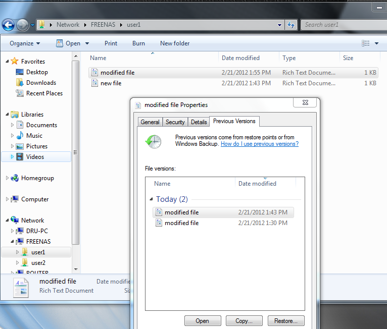
Fig. 9.4.5 Viewing Previous Versions within Explorer
9.5. Block (iSCSI)
iSCSI is a protocol standard for the consolidation of storage data. iSCSI allows TrueNAS® to act like a storage area network (SAN) over an existing Ethernet network. Specifically, it exports disk devices over an Ethernet network that iSCSI clients (called initiators) can attach to and mount. Traditional SANs operate over fibre channel networks which require a fibre channel infrastructure such as fibre channel HBAs, fibre channel switches, and discrete cabling. iSCSI can be used over an existing Ethernet network, although dedicated networks can be built for iSCSI traffic in an effort to boost performance. iSCSI also provides an advantage in an environment that uses Windows shell programs; these programs tend to filter “Network Location” but iSCSI mounts are not filtered.
Before configuring the iSCSI service, be familiar with this iSCSI terminology:
CHAP: an authentication method which uses a shared secret and three-way authentication to determine if a system is authorized to access the storage device and to periodically confirm that the session has not been hijacked by another system. In iSCSI, the initiator (client) performs the CHAP authentication.
Mutual CHAP: a superset of CHAP in that both ends of the communication authenticate to each other.
Initiator: a client which has authorized access to the storage data on the TrueNAS® system. The client requires initiator software to initiate the connection to the iSCSI share.
Target: a storage resource on the TrueNAS® system. Every target has a unique name known as an iSCSI Qualified Name (IQN).
Internet Storage Name Service (iSNS): protocol for the automated discovery of iSCSI devices on a TCP/IP network.
Extent: the storage unit to be shared. It can either be a file or a device.
Portal: indicates which IP addresses and ports to listen on for connection requests.
LUN: Logical Unit Number representing a logical SCSI device. An initiator negotiates with a target to establish connectivity to a LUN. The result is an iSCSI connection that emulates a connection to a SCSI hard disk. Initiators treat iSCSI LUNs as if they were a raw SCSI or SATA hard drive. Rather than mounting remote directories, initiators format and directly manage filesystems on iSCSI LUNs. When configuring multiple iSCSI LUNs, create a new target for each LUN. Since iSCSI multiplexes a target with multiple LUNs over the same TCP connection, there can be TCP contention when more than one target accesses the same LUN. TrueNAS® supports up to 1024 LUNs.
ALUA: Asymmetric Logical Unit Access allows a client computer to discover the best path to the storage on a TrueNAS® system. HA storage clusters can provide multiple paths to the same storage. For example, the disks are directly connected to the primary computer and provide high speed and bandwidth when accessed through that primary computer. The same disks are also available through the secondary computer, but because they are not directly connected to it, speed and bandwidth are restricted. With ALUA, clients automatically ask for and use the best path to the storage. If one of the TrueNAS® HA computers becomes inaccessible, the clients automatically switch to the next best alternate path to the storage. When a better path becomes available, as when the primary host becomes available again, the clients automatically switch back to that better path to the storage.
Note
Do not enable ALUA on TrueNAS® unless it is supported by and enabled on the client computers also. ALUA only works properly when enabled on both the client and server.
In TrueNAS®, iSCSI is built into the kernel. This version of iSCSI supports Microsoft Offloaded Data Transfer (ODX), meaning that file copies happen locally, rather than over the network. It also supports the VAAI (vStorage APIs for Array Integration) primitives for efficient operation of storage tasks directly on the NAS. To take advantage of the VAAI primitives, create a zvol using the instructions in Create zvol and use it to create a device extent, as described in Extents.
To configure iSCSI:
- Review the target global configuration parameters.
- Create at least one portal.
- Determine which hosts are allowed to connect using iSCSI and create an initiator.
- Decide if authentication will be used, and if so, whether it will be CHAP or mutual CHAP. If using authentication, create an authorized access.
- Create a target.
- Create either a device or a file extent to be used as storage.
- Associate a target with an extent.
- Start the iSCSI service in .
The rest of this section describes these steps in more detail.
Note
If the system has been licensed for Fibre Channel, the screens will vary slightly from those found in the rest of this section. Refer to the section on Fibre Channel Ports for details.
9.5.1. Target Global Configuration
, shown in Figure 9.5.1, contains settings that apply to all iSCSI shares. Table 9.5.1 summarizes the settings that are configured in the Target Global Configuration screen.
Some built-in values affect iSNS usage. Fetching of allowed initiators from iSNS is not implemented, so target ACLs must be configured manually. To make iSNS registration useful, iSCSI targets should have explicitly configured port IP addresses. This avoids initiators attempting to discover unconfigured target portal addresses like 0.0.0.0.
The iSNS registration period is 900 seconds. Registered Network Entities not updated during this period are unregistered. The timeout for iSNS requests is 5 seconds.
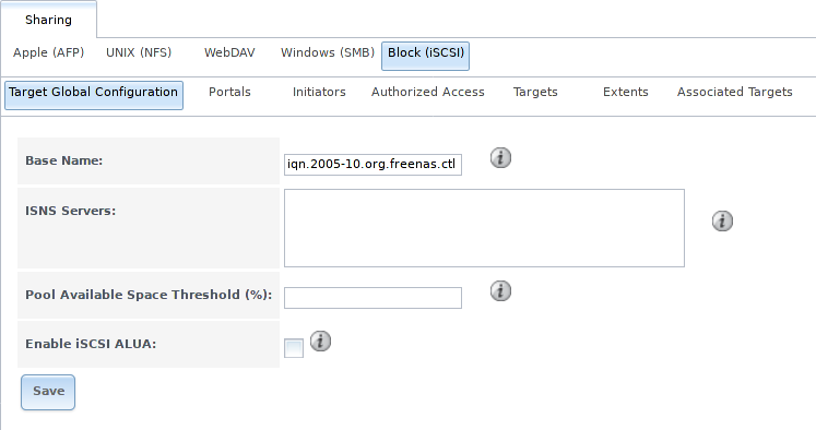
Fig. 9.5.1 iSCSI Target Global Configuration Variables
| Setting | Value | Description |
|---|---|---|
| Base Name | string | Lowercase alphanumeric characters plus dot (.), dash (-), and colon (:) are allowed. See the “Constructing iSCSI names using the iqn. format” section of RFC 3721. |
| ISNS Servers | string | Enter the hostnames or IP addresses of ISNS servers to be registered with iSCSI targets and portals of the system. Separate each entry with a space. |
| Pool Available Space Threshold | integer | Enter the percentage of free space to in the pool. When this percentage is reached, the system issues an alert, but only if zvols are used. See VAAI Threshold Warning for more information. |
| Enable iSCSI ALUA | checkbox | Enable ALUA for automatic best path discovery when supported by clients. This option is only available on HA systems. |
9.5.2. Portals
A portal specifies the IP address and port number to be used for iSCSI connections. brings up the screen shown in Figure 9.5.2.
Table 9.5.2 summarizes the settings that can be configured when adding a portal. To assign additional IP addresses to the portal, click the link Add extra Portal IP.
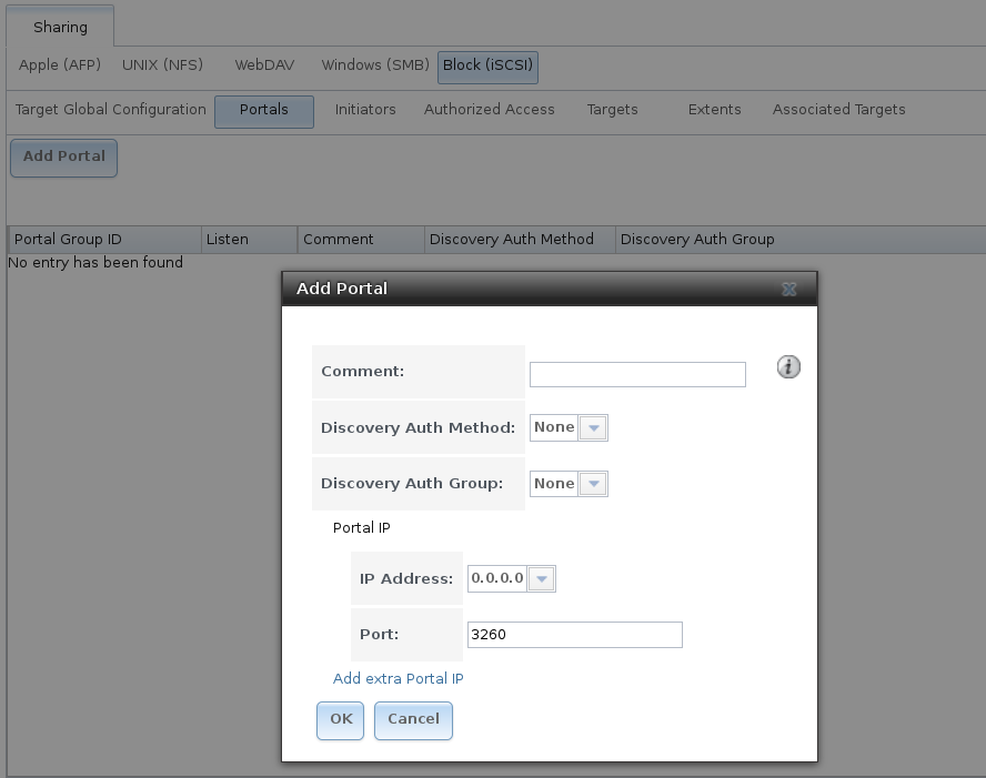
Fig. 9.5.2 Adding an iSCSI Portal
| Setting | Value | Description |
|---|---|---|
| Comment | string | Optional description. Portals are automatically assigned a numeric group ID. |
| Discovery Auth Method | drop-down menu | iSCSI supports multiple authentication methods that are used by the target to discover valid devices. None allows anonymous discovery while CHAP and Mutual CHAP both require authentication. |
| Discovery Auth Group | drop-down menu | Select a user created in Authorized Access if the Discovery Auth Method is set to CHAP or Mutual CHAP. |
| IP address | drop-down menu | Select the IPv4 or IPv6 address associated with an interface or the wildcard address of 0.0.0.0 (any interface). |
| Port | integer | TCP port used to access the iSCSI target. Default is 3260. |
TrueNAS® systems with multiple IP addresses or interfaces can use a portal to provide services on different interfaces or subnets. This can be used to configure multi-path I/O (MPIO). MPIO is more efficient than a link aggregation.
If the TrueNAS® system has multiple configured interfaces, portals can also be used to provide network access control. For example, consider a system with four interfaces configured with these addresses:
192.168.1.1/24
192.168.2.1/24
192.168.3.1/24
192.168.4.1/24
A portal containing the first two IP addresses (group ID 1) and a portal containing the remaining two IP addresses (group ID 2) could be created. Then, a target named A with a Portal Group ID of 1 and a second target named B with a Portal Group ID of 2 could be created. In this scenario, the iSCSI service would listen on all four interfaces, but connections to target A would be limited to the first two networks and connections to target B would be limited to the last two networks.
Another scenario would be to create a portal which includes every IP address except for the one used by a management interface. This would prevent iSCSI connections to the management interface.
9.5.3. Initiators
The next step is to configure authorized initiators, or the systems which are allowed to connect to the iSCSI targets on the TrueNAS® system. To configure which systems can connect, use , shown in Figure 9.5.3.
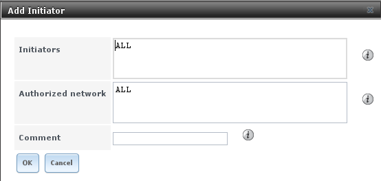
Fig. 9.5.3 Adding an iSCSI Initiator
Table 9.5.3 summarizes the settings that can be configured when adding an initiator.
| Setting | Value | Description |
|---|---|---|
| Initiators | string | Use ALL keyword or a list of initiator hostnames separated by spaces. |
| Authorized network | string | Network addresses that can use this initiator. Use ALL or
list network addresses with a CIDR mask.
Separate multiple addresses with a space:
192.168.2.0/24 192.168.2.1/12. |
| Comment | string | Notes or a description of the initiator. |
In the example shown in Figure 9.5.4, two groups are created. Group 1 allows connections from any initiator on any network. Group 2 allows connections from any initiator on the 10.10.1.0/24 network. Click an initiator’s entry to display its Edit and Delete buttons.
Note
Attempting to delete an initiator causes a warning that indicates if any targets or target/extent mappings depend upon the initiator. Confirming the delete causes these to be deleted also.
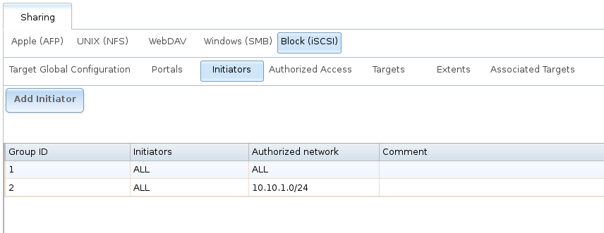
Fig. 9.5.4 Sample iSCSI Initiator Configuration
9.5.4. Authorized Accesses
When using CHAP or mutual CHAP to provide authentication, creating an authorized access in is recommended. This screen is shown in Figure 9.5.5.
Note
This screen sets login authentication. This is different from discovery authentication which is set in Target Global Configuration.
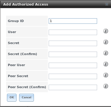
Fig. 9.5.5 Adding an iSCSI Authorized Access
Table 9.5.4 summarizes the settings that can be configured when adding an authorized access:
| Setting | Value | Description |
|---|---|---|
| Group ID | integer | Allows different groups to be configured with different authentication profiles. Example: all users with a Group ID of 1 will inherit the authentication profile associated with Group 1. |
| User | string | Enter name of user account to create for CHAP authentication with the user on the remote system. Many initiators default to using the initiator name as the user. |
| Secret | string | Enter a password for User. The iSCSI standard requires that this be between 12 and 16 characters. |
| Peer User | string | Only input when configuring mutual CHAP. In most cases it will need to be the same value as User. |
| Peer Secret | string | Enter the mutual secret password which must be different than the Secret. Required if Peer User is set. |
Note
CHAP does not work with GlobalSAN initiators on macOS.
As authorized accesses are added, they will be listed under View Authorized Accesses. In the example shown in Figure 9.5.6, three users (test1, test2, and test3) and two groups (1 and 2) are created, with group 1 consisting of one CHAP user and group 2 consisting of one mutual CHAP user and one CHAP user. Click an authorized access entry to display its Edit and Delete buttons.
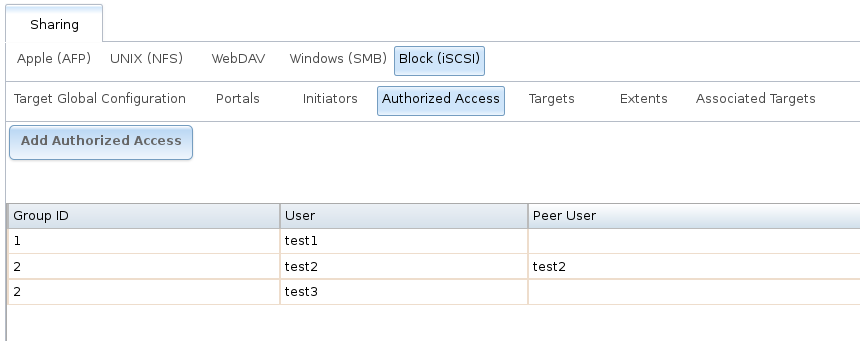
Fig. 9.5.6 Viewing Authorized Accesses
9.5.5. Targets
Next, create a Target using , as shown in Figure 9.5.7. A target combines a portal ID, allowed initiator ID, and an authentication method. Table 9.5.5 summarizes the settings that can be configured when creating a Target.
Note
An iSCSI target creates a block device that may be accessible to multiple initiators. A clustered filesystem is required on the block device, such as VMFS used by VMware ESX/ESXi, in order for multiple initiators to mount the block device read/write. If a traditional filesystem such as EXT, XFS, FAT, NTFS, UFS, or ZFS is placed on the block device, care must be taken that only one initiator at a time has read/write access or the result will be filesystem corruption. If multiple clients need access to the same data on a non-clustered filesystem, use SMB or NFS instead of iSCSI, or create multiple iSCSI targets (one per client).
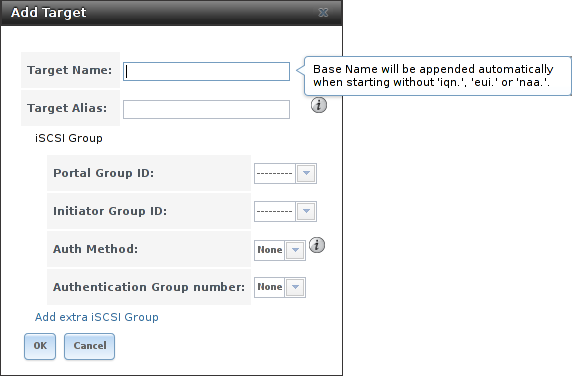
Fig. 9.5.7 Adding an iSCSI Target
| Setting | Value | Description |
|---|---|---|
| Target Name | string | Required. The base name is automatically prepended if the target name does not start with iqn. Lowercase alphanumeric characters plus dot (.), dash (-), and colon (:) are allowed. See the “Constructing iSCSI names using the iqn. format” section of RFC 3721. |
| Target Alias | string | Enter an optional user-friendly name. |
| Portal Group ID | drop-down menu | Leave empty or select number of existing portal to use. |
| Initiator Group ID | drop-down menu | Select which existing initiator group has access to the target. |
| Auth Method | drop-down menu | Choices are: None, Auto, CHAP, or Mutual CHAP. |
| Authentication Group number | drop-down menu | Select None or an integer. This number represents the number of existing authorized accesses. |
9.5.6. Extents
iSCSI targets provide virtual access to resources on the TrueNAS® system. Extents are used to define resources to share with clients. There are two types of extents: device and file.
Device extents provide virtual storage access to zvols, zvol snapshots, or physical devices like a disk, an SSD, a hardware RAID volume, or a HAST device.
File extents provide virtual storage access to an individual file.
Tip
For typical use as storage for virtual machines where the virtualization software is the iSCSI initiator, device extents with zvols provide the best performance and most features. For other applications, device extents sharing a raw device can be appropriate. File extents do not have the performance or features of device extents, but do allow creating multiple extents on a single filesystem.
Virtualized zvols support all the TrueNAS® VAAI primitives and are recommended for use with virtualization software as the iSCSI initiator.
The ATS, WRITE SAME, XCOPY and STUN, primitives are supported by both file and device extents. The UNMAP primitive is supported by zvols and raw SSDs. The threshold warnings primitive is fully supported by zvols and partially supported by file extents.
Virtualizing a raw device like a single disk or hardware RAID volume limits performance to the abilities of the device. Because this bypasses ZFS, such devices do not benefit from ZFS caching or provide features like block checksums or snapshots.
Virtualizing a zvol adds the benefits of ZFS, such as read and write cache. Even if the client formats a device extent with a different filesystem, the data still resides on a ZFS volume and benefits from ZFS features like block checksums and snapshots.
Warning
For performance reasons and to avoid excessive fragmentation, keep the used space of the pool below 80% when using iSCSI. The capacity of an existing extent can be increased as shown in Growing LUNs.
To add an extent, go to
.
In the example shown in
Figure 9.5.8,
the device extent is using the export zvol that was previously
created from the /mnt/volume1 volume.
Table 9.5.6 summarizes the settings that can be configured when creating an extent. Note that file extent creation fails when the name of the file to be created to the volume/dataset name. is not appended.
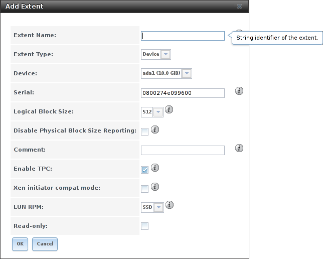
Fig. 9.5.8 Adding an iSCSI Extent
| Setting | Value | Description |
|---|---|---|
| Extent Name | string | Enter the extent name. If the Extent size is not 0, it cannot be an existing file within the volume/dataset. |
| Extent Type | drop-down menu | Select from File or Device. |
| Device | drop-down menu | Only appears if Device is selected. Select the unformatted disk, controller, zvol, zvol snapshot, or HAST device. |
| Serial | string | Unique LUN ID. The default is generated from the system MAC address. |
| Path to the extent | browse button | Only appears if File is selected. Browse to an existing file and use 0 as the Extent size, or browse to the volume or dataset, click Close, append the Extent Name to the path, and specify a value in Extent size. Extents cannot be created inside the jail root directory. |
| Extent size | integer | Only appears if File is selected. If the size is specified as 0, the file must already exist and the actual file size will be used. Otherwise, specify the size of the file to create. |
| Logical Block Size | drop-down menu | Only override the default if the initiator requires a different block size. |
| Disable Physical Block Size Reporting | checkbox | Set if the initiator does not support physical block size values over 4K (MS SQL). Setting can also prevent constant block size warnings when using this share with ESXi. |
| Available Space Threshold | string | Only appears if File or a zvol is selected. When the specified percentage of free space is reached, the system issues an alert. See VAAI Threshold Warning for more information. |
| Comment | string | Enter an optional comment. |
| Enable TPC | checkbox | If enabled, an initiator can bypass normal access control and access any scannable target. This allows xcopy operations otherwise blocked by access control. |
| Xen initiator compat mode | checkbox | Set this option when using Xen as the iSCSI initiator. |
| LUN RPM | drop-down menu | Do NOT change this setting when using Windows as the initiator. Only needs to be changed in large environments where the number of systems using a specific RPM is needed for accurate reporting statistics. |
| Read-only | checkbox | Set to prevent the initiator from initializing this LUN . |
9.5.7. Target/Extents
The last step is associating an extent to a target within . This screen is shown in Figure 9.5.9. Use the drop-down menus to select the existing target and extent. Click OK to add an entry for the LUN.
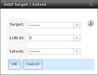
Fig. 9.5.9 Associating a Target With an Extent
Table 9.5.7 summarizes the settings that can be configured when associating targets and extents.
| Setting | Value | Description |
|---|---|---|
| Target | drop-down menu | Select an existing target. |
| LUN ID | integer | Type a value between 0 and 1023. Note that some initiators expect a value below 256. Enter 0 to statically assign the next available ID. |
| Extent | drop-down menu | Select an existing extent. |
Always associating extents to targets in a one-to-one manner is recommended, even though the GUI will allow multiple extents to be associated with the same target.
Note
Each LUN entry has Edit and Delete buttons for modifying the settings or deleting the LUN entirely. A verification popup appears when the Delete button is clicked. If an initiator has an active connection to the LUN, it is indicated in red text. Clearing initiator connections to a LUN before deleting it is recommended.
After iSCSI has been configured, remember to start it in . Click the red OFF button next to iSCSI. After a second or so, it will change to a blue ON, indicating that the service has started.
9.5.8. Fibre Channel Ports
If the TrueNAS® system has Fibre Channel ports, will appear as and an extra Fibre Channel Ports tab is added. An example is shown in Figure 9.5.10.
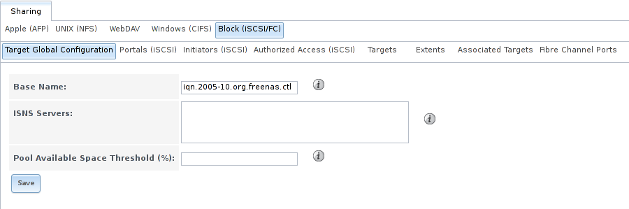
Fig. 9.5.10 Block (iSCSI) Screen
Otherwise, the Target Global Configuration screen is the same as described in Target Global Configuration.
Since the Portals, Initiators, and Authorized Access screens only apply to iSCSI, they are marked as such and can be ignored when configuring Fibre Channel.
As seen in Figure 9.5.11, the screen has an extra Target Mode option for indicating whether the target to create is iSCSI, Fibre Channel, or both.
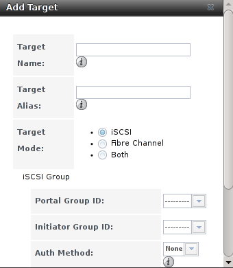
Fig. 9.5.11 Add Target Screen
After selecting Fibre Channel, this screen changes so only the Target Name and Target Alias fields remain, as those are the only applicable fields for a Fibre Channel connection. An example is shown in Figure 9.5.12.
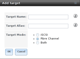
Fig. 9.5.12 Configuring a Fibre Channel Target
The screens for adding an extent and associating a target are the same as described in Extents and Target/Extents.
An example of the Fibre Channel Ports screen is shown in Figure 9.5.13.
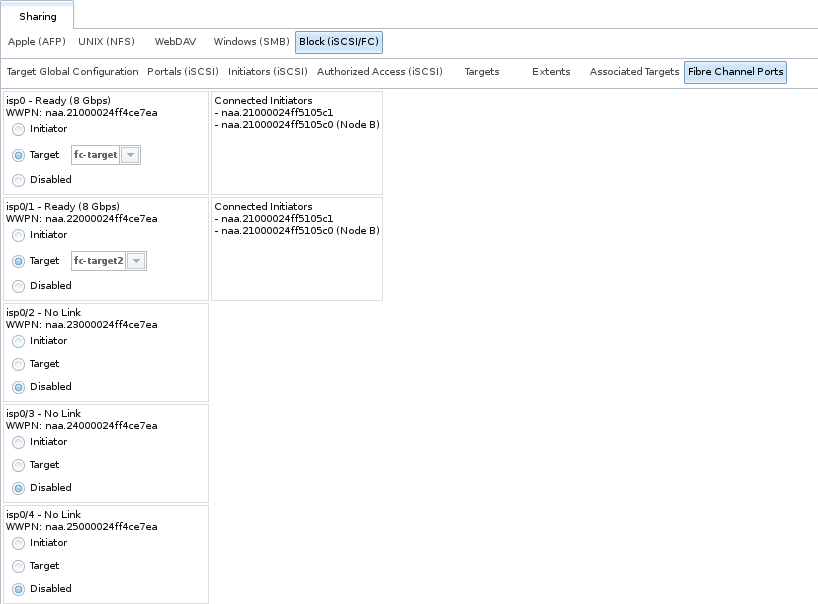
Fig. 9.5.13 Configuring a Fibre Channel Port
This screen shows the status of each attached fibre channel port, where:
- Initiator: indicates that the port is acting as a client and has access to any physically attached storage.
- Target: indicates that clients are connecting to the specified target through this port.
- Disabled: indicates that this fibre channel port is not in use.
Note
The Target tab of Reporting provides Fibre Channel port bandwidth graphs.
This example has also been configured for NPIV (N_Port ID Virtualization). Note that the physical interface isp0 has two virtual ports (isp0/1 and isp0/2) displayed in Figure 9.5.13:. NPIV allows the administrator to use switch zoning to configure each virtual port as if it was a physical port in order to provide access control. This is important in an environment with a mix of Windows systems and virtual machines in order to prevent automatic or accidental reformatting of targets containing unrecognized filesystems. It can also be used to segregate data; for example, to prevent the engineering department from accessing data from the human resources department. Refer to the switch documentation for details on how to configure zoning of virtual ports.
To create the virtual ports on the TrueNAS® system, go to and enter the following:
- Variable: input hint.isp.X.vports, replacing X with the number of the physical interface.
- Value: input the number of virtual ports to create. Note that there cannot be more then 125 SCSI target ports and that number includes all physical Fibre Channel ports, all virtual ports, and all configured combinations of iSCSI portals and targets.
- Type: make sure loader is selected.
In the example shown in Figure 9.5.14, two physical interfaces were each assigned 4 virtual ports. Note that two tunables were required, one for each physical interface. After the tunables are created, the configured number of virtual ports appears in the Fibre Channel Ports screen so they can be associated with targets. They will also be advertised to the switch so zoning can be configured on the switch. After a virtual port has been associated with a target, it is added to the Target tab of Reporting where its bandwidth usage can be viewed.
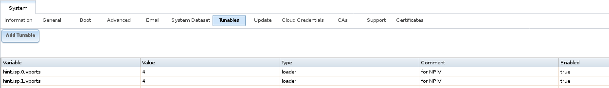
Fig. 9.5.14 Adding Virtual Ports
9.5.9. Connecting to iSCSI
To access the iSCSI target, clients must use iSCSI initiator software.
An iSCSI Initiator client is pre-installed with Windows 7. A detailed how-to for this client can be found here. A client for Windows 2000, XP, and 2003 can be found here. This how-to shows how to create an iSCSI target for a Windows 7 system.
macOS does not include an initiator. globalSAN is a commercial, easy-to-use Mac initiator.
BSD systems provide command line initiators: iscontrol(8) comes with FreeBSD versions 9.x and lower, iscsictl(8) comes with FreeBSD versions 10.0 and higher, iscsi-initiator(8) comes with NetBSD, and iscsid(8) comes with OpenBSD.
Some Linux distros provide the command line utility iscsiadm from Open-iSCSI. Use a web search to see if a package exists for the distribution should the command not exist on the Linux system.
If a LUN is added while iscsiadm is already connected, it will not see the new LUN until rescanned with iscsiadm -m node -R. Alternately, use iscsiadm -m discovery -t st -p portal_IP to find the new LUN and iscsiadm -m node -T LUN_Name -l to log into the LUN.
Instructions for connecting from a VMware ESXi Server can be found at How to configure FreeNAS 8 for iSCSI and connect to ESX(i). Note that the requirements for booting vSphere 4.x off iSCSI differ between ESX and ESXi. ESX requires a hardware iSCSI adapter while ESXi requires specific iSCSI boot firmware support. The magic is on the booting host side, meaning that there is no difference to the TrueNAS® configuration. See the iSCSI SAN Configuration Guide for details.
The VMware firewall only allows iSCSI connections on port 3260 by default. If a different port has been selected, outgoing connections to that port must be manually added to the firewall before those connections will work.
If the target can be seen but does not connect, check the Discovery Auth settings in Target Global Configuration.
If the LUN is not discovered by ESXi, make sure that promiscuous mode is set to Accept in the vSwitch.
9.5.10. Growing LUNs
The method used to grow the size of an existing iSCSI LUN depends on whether the LUN is backed by a file extent or a zvol. Both methods are described in this section.
Enlarging a LUN with one of the methods below gives it more unallocated space, but does not automatically resize filesystems or other data on the LUN. This is the same as binary-copying a smaller disk onto a larger one. More space is available on the new disk, but the partitions and filesystems on it must be expanded to use this new space. Resizing virtual disk images is usually done from virtual machine management software. Application software to resize filesystems is dependent on the type of filesystem and client, but is often run from within the virtual machine. For instance, consider a Windows VM with the last partition on the disk holding an NTFS filesystem. The LUN is expanded and the partition table edited to add the new space to the last partition. The Windows disk manager must still be used to resize the NTFS filesystem on that last partition to use the new space.
9.5.10.1. Zvol Based LUN
To grow a zvol based LUN, go to , highlight the zvol to be grown, and click Edit zvol. In the example shown in Figure 9.5.15, the current size of the zvol named zvol1 is 4 GiB.
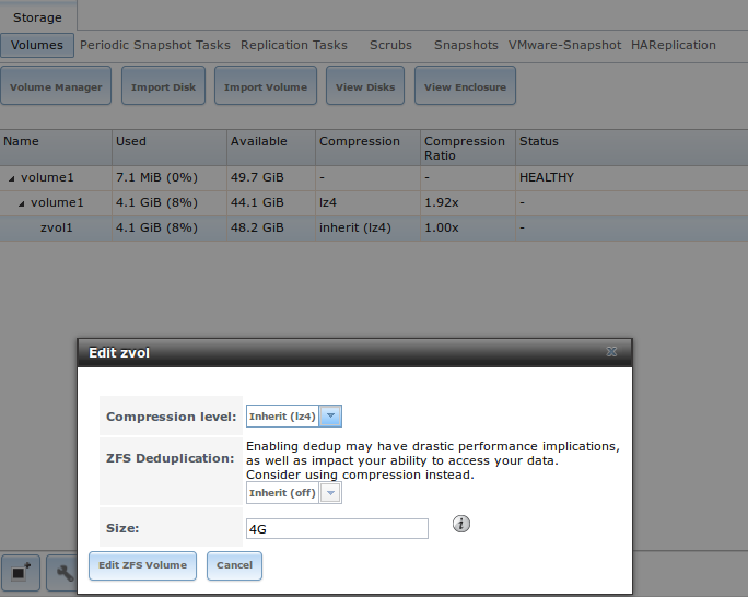
Fig. 9.5.15 Editing an Existing Zvol
Enter the new size for the zvol in the Size field and click Edit ZFS Volume. This menu closes and the new size for the zvol is immediately shown in the Used column of the View Volumes screen.
Note
The GUI does not allow reducing (shrinking) the size of the zvol, as doing so could result in loss of data. It also does not allow increasing the size of the zvol past 80% of the volume size.
9.5.10.2. File Extent Based LUN
To grow a file extent based LUN, go to
to determine the path of the file extent to
grow. Open Shell to grow the extent. This example
grows /mnt/volume1/data by 2 G:
truncate -s +2g /mnt/volume1/data
Go back to and click the Edit button for the file extent. Set the size to 0 as this causes the iSCSI target to use the new size of the file.
9.6. Creating Authenticated and Time Machine Shares
macOS includes the Time Machine feature which performs automatic back ups. TrueNAS® supports Time Machine backups for both SMB and AFP shares. This section has instructions to create Time Machine SMB and AFP shares, using the to create an AFP Time Machine share. The process for creating an authenticated share for a user is the same as creating a Time Machine share for that user.
9.6.2. Create AFP Time Machine Share with the Wizard
To use the Wizard to create an AFP authenticated or Time Machine share, enter the following information, as seen in the example in Figure 9.6.1.
- Share name: enter a name for the share that is identifiable but less than 27 characters long. The name cannot contain a period. In this example, the share is named backup_user1.
- Click the button for Mac OS X (AFP) and enable the Time Machine option.
- Click the Ownership button. If the user already exists on the TrueNAS® system, click the drop-down User menu to select their user account. If the user does not yet exist on the TrueNAS® system, type their name into the User field and enable the Create User option. If the user is a member of a group that already exists on the TrueNAS® system, click the drop-down Group menu to select the group name. To create a new group to be used by Time Machine users, enter the name in the Group field and set the Create Group option. Otherwise, enter the same name as the user. In the example shown in Figure 9.6.2, both a new user1 user and a new tm_backups group are created. Since a new user is being created, this screen prompts for the user password to be used when accessing the share. It also provides an opportunity to change the default permissions on the share. When finished, click Return to return to the screen shown in Figure 9.6.1.
- Click the Add button.
When creating multiple authenticated or Time Machine shares, repeat this process for each user. Give each user their own Share name and Ownership. When finished, click the Next button twice, then the Confirm button to create the shares. The Wizard creates a dataset for each share with the correct ownership and starts the AFP service so the shares are immediately available. The new shares appear in .

Fig. 9.6.1 Creating a Time Machine Share
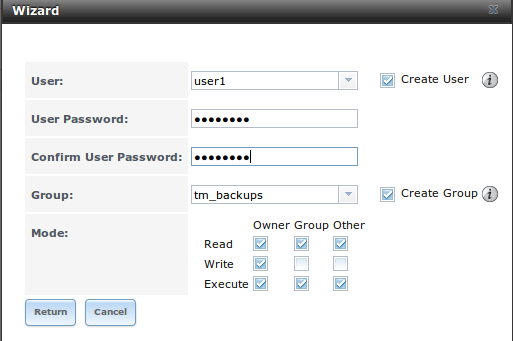
Fig. 9.6.2 Creating an Authenticated User
9.6.3. Configuring Time Machine Backups
Configuring a quota for each Time Machine share helps prevent backups from using all available space on the TrueNAS® system. Time Machine creates ongoing hourly, daily, weekly, and monthly backups. The oldest backups are deleted when a Time Machine share fills up, so make sure that the quota size is large enough to hold the desired number of backups. Note that a default installation of macOS is over 20 GiB.
Configure a global quota using the instructions in Set up Time Machine for multiple machines with OSX Server-Style Quotas.
To configure a quota, go to and select the share dataset. In the example shown in Figure 9.6.3, the Time Machine share name is backup_user1. Click the Edit Options button for the share, then Advanced Mode. Enter a value in the Quota for this dataset field, then click Edit Dataset to save the change. In this example, the Time Machine share is restricted to 200 GiB.
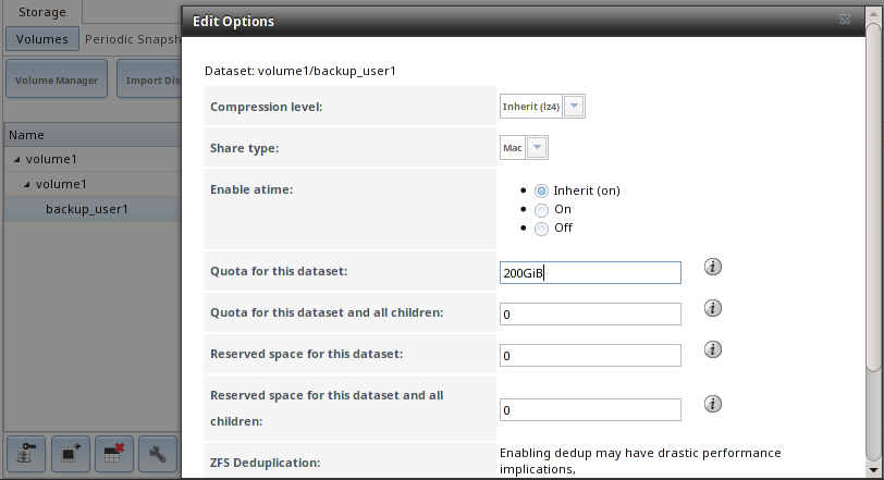
Fig. 9.6.3 Setting a Quota
To configure Time Machine on the macOS client, go to , which opens the screen shown in Figure 9.6.4. Click ON and a pop-up menu shows the TrueNAS® system as a backup option. In this example, it is listed as backup_user1 on “freenas”. Highlight the TrueNAS® system and click Use Backup Disk. A connection bar opens and prompts for the user account’s password. In this example, the password is the password that was set for the user1 account.
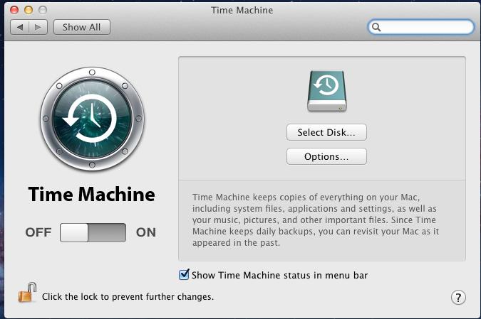
Fig. 9.6.4 Configuring Time Machine on Mac OS X Lion
If Time Machine could not complete the backup. The backup disk
image could not be created (error 45) is shown when backing up to the
TrueNAS® system, a sparsebundle image must be created using
these instructions.
If Time Machine completed a verification of your backups. To
improve reliability, Time Machine must create a new backup for you. is
shown, follow the instructions in this post
to avoid making another backup or losing past backups.