16. Hardware Setup
The TrueNAS® M-Series (M40 and M50) consists of one or two 4U units. Optional ES12, ES24, or ES60 Expansion Shelves can be added to expand storage capacity.
The TrueNAS® X-Series (X10 and X20) consists of one or two 2U units. Optional Expansion Shelves can be added to expand storage capacity. The X10 supports the ES12 Expansion Shelf and the X20 supports the ES12, ES24, and ES60 Expansion Shelves.
Deployment Guides and data sheets for the M-Series, X-Series, Expansion Shelves, as well as EoL products, are available at https://www.ixsystems.com/blog/knowledgebase_category/truenas/.
Racking and connection information for the M-Series, X-Series, and Expansion Shelves is described below.
Note
Always perform the initial TrueNAS® setup in consultation with an iXsystems Support Representative.
16.1. Contacting iXsystems
For assistance, please contact iX Support:
| Contact Method | Contact Options |
|---|---|
| Web | https://support.ixsystems.com |
support@iXsystems.com |
|
| Telephone | Monday - Friday, 8:00AM to 5:00PM Pacific Standard Time:
|
| Telephone | After Hours (24x7 Gold Level Support only):
|
Copyright © 2019 iXsystems, Inc. All rights reserved.
All trademarks are the property of their respective owners.
16.2. M-Series Unified Storage Array
The TrueNAS® M-Series Unified Storage Array is a 4U, 24-bay, hybrid data storage array.
Note
TrueNAS® units are carefully packed and shipped with
trusted carriers to arrive in perfect condition. If there is any
shipping damage or any parts are missing, please take photos and
contact iXsystems support immediately at
support@iXsystems.com or 1-855-GREP4-iX
(1-855-473-7449) or 1-408-943-4100.
Please locate and record the hardware serial numbers on the back or side of each chassis for easy reference.
Carefully unpack the shipping boxes and locate these components:
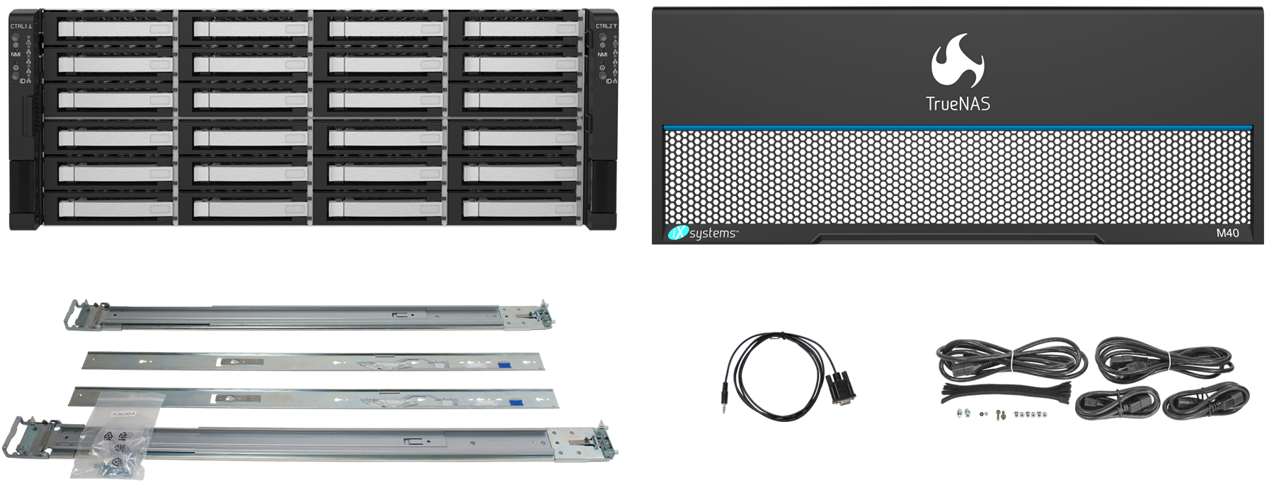
M-Series Unified Storage Array, M-Series Bezel, set of rackmount rails, up to 24 drive trays populated with drives, DB9 to 3.5mm serial cable, and an accessory kit with 2 IEC C13 to NEMA 5-15P power cords, 2 IEC C14 to C13 cords, velcro cable ties, M4x4L screws, M5x18 screws, screw posts, and alternate pins for round hole racks.
16.2.1. Become Familiar With the M-Series System
The M-Series has front panel indicators for power, locate ID, and fault. The fault indicator is on during the initial power-on self-test (POST) and turns off during normal operation. It turns on if the TrueNAS® software issues an alert. See the Alert section in the Additional Options chapter of the TrueNAS® User Guide.
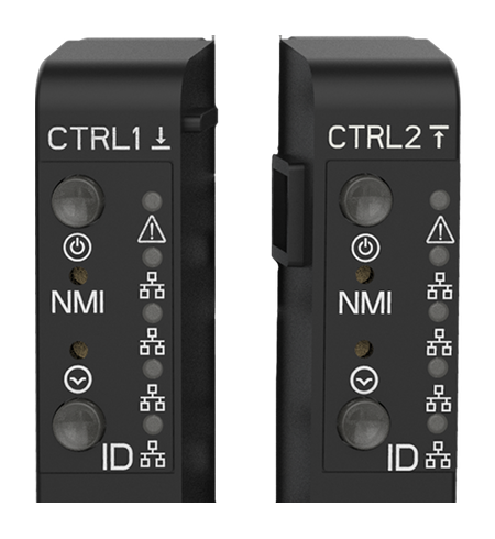
The M-Series has one or two storage controllers in an over-and-under configuration. Examples of typical M40 (top) and M50 (bottom) models are shown here.
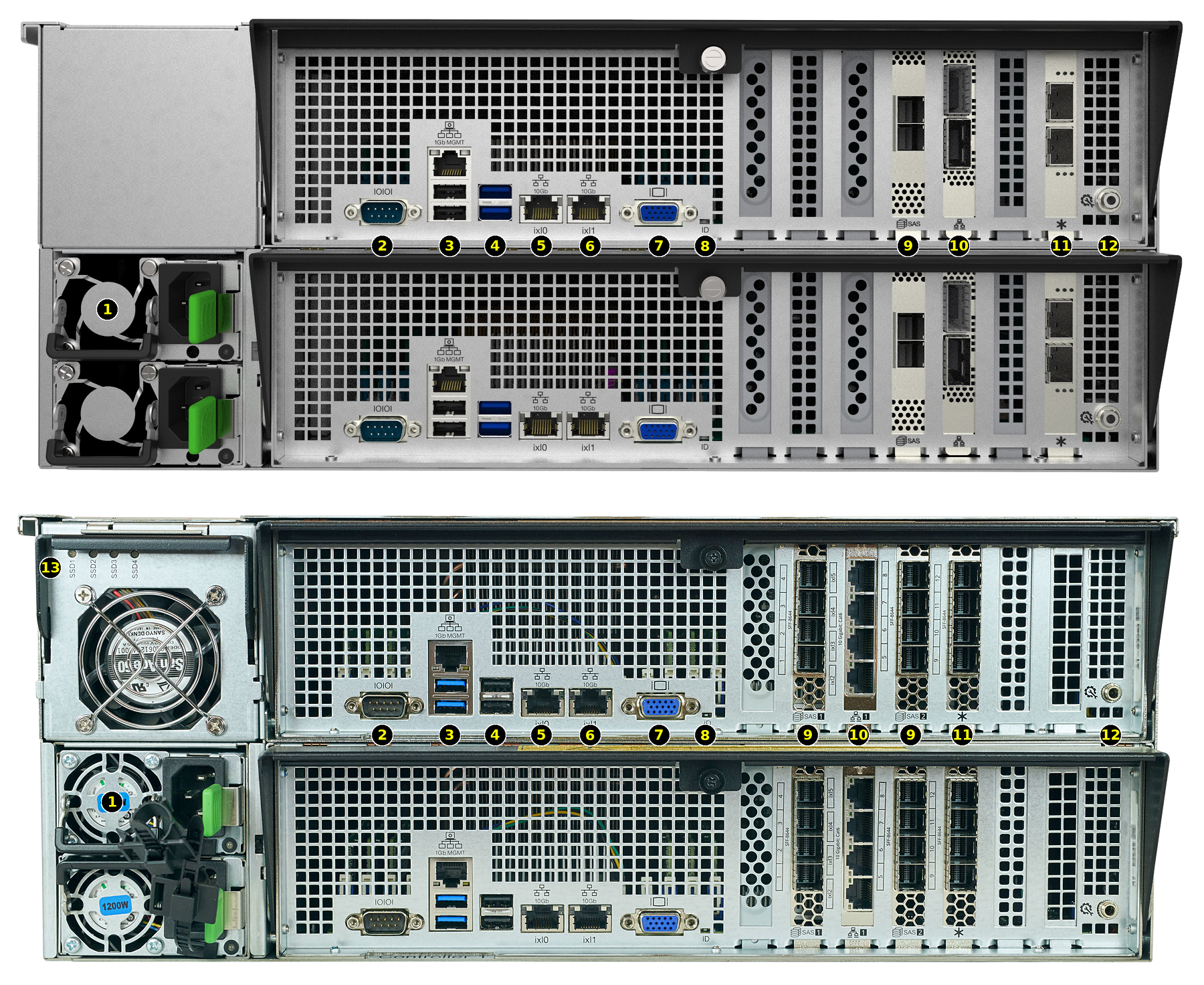
| 1: Redundant power supplies | 8: ID LED |
| 2: Serial port | 9: HD Mini SAS3 connectors |
| 3: 1Gb Ethernet Out of Band (OOB) dedicated management port, dual USB 2.0 ports | 10: Networking port |
| 4: Dual USB 3.0 ports | 11: Asterisk slot: Fibre Channel or additional networking |
| 5: 10Gb Ethernet port | 12: Storage controller management port |
| 6: 10Gb Ethernet port | 13: NVMe activity indicators |
| 7: VGA monitor port | |
M-Series systems with only a single storage controller must be shut down and powered off before removing the controller, or data stored in the NVDIMM SLOG will be lost! Dual storage controller systems synchronize data between each NVDIMM, but can lose data if both controllers are removed before being properly shut down.
For remote management with IPMI, the 1 Gb Ethernet Out of Band management port (#3) must be connected to a network.
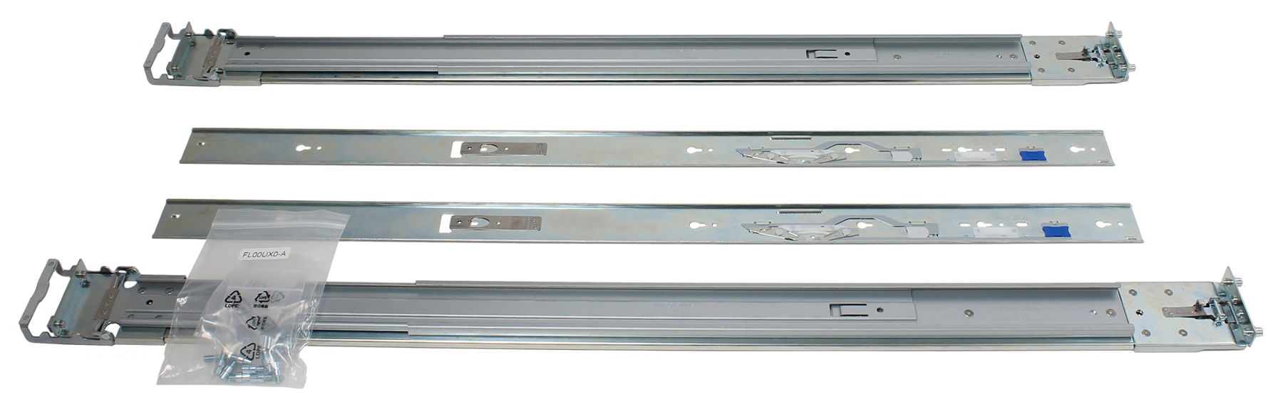
16.2.2. ES24 and M-Series Rail Kit Assembly
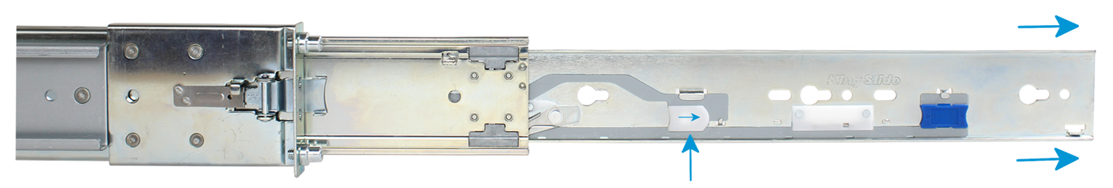
16.2.2.1. Remove Cabinet Rails from Rack Rails
Extend the cabinet rail until it stops. To remove the cabinet rail, press the white release tab to the right while pulling the cabinet rail.
16.2.2.2. Mount Cabinet Rails
The cabinet rails are mounted on both sides of the system cabinet. Align the cabinet rail keyholes with the three posts (ES24) or four posts (M-Series) on the side of the chassis and slide the rail until the post is secured in the keyhole slot of the rail.
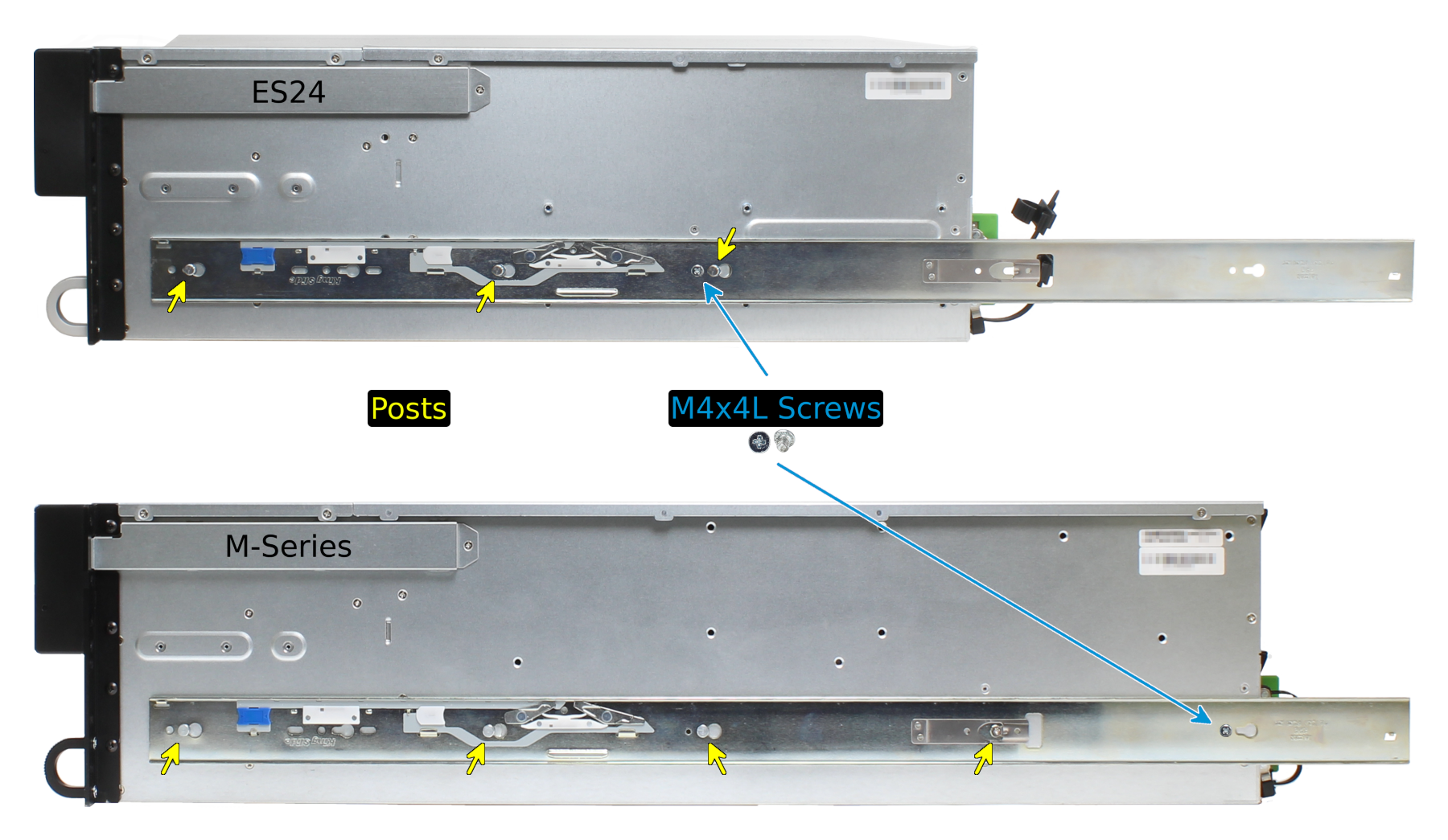
Align the rail hole with the screw hole and secure the rail with one M4x4L screw from the rail kit. Repeat this process to mount and secure the second cabinet rail on the other side.
16.2.2.3. Mount the Rack Rails
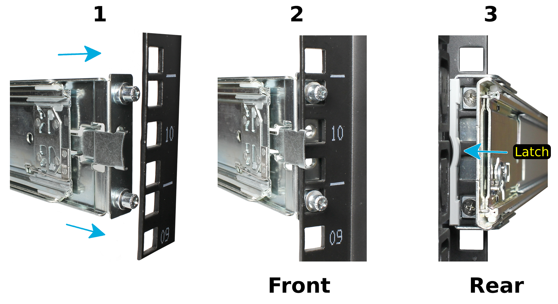
Place the rail in the rack with the front end toward the front of the rack, aligning the pins with the mounting holes in the front of the rack. Push the pins into the holes until the latch clicks.
For the rear end of the rail, align the pins with the mounting holes on the rear rack. Pull the white latch toward the rear until the pins click in place. Repeat this process for the second rear rail.
16.2.2.4. Mount the Unit in the Rack
Caution: Two people are required to safely lift the chassis for rack installation or removal. Do not install drives until after the chassis has been installed in the rack, and remove all drives before removing the chassis from the rack.
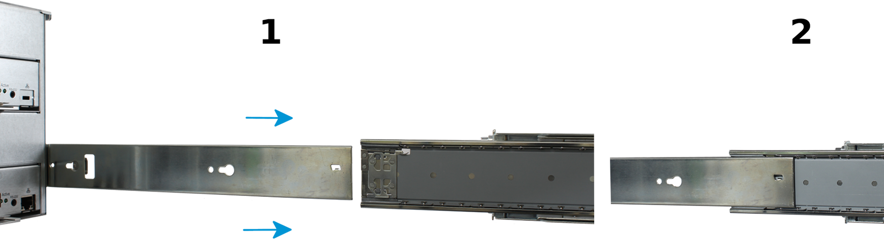
Pull the front rack rail forward until it stops. Align the cabinet rail with the inside of the front rack rail and slide the cabinet rail forward until it is fully seated inside the rack rail. Repeat the process for the second rail.
When both cabinet rails are secured in the rack rails, gently push the chassis until it stops halfway in. Slide the blue release tabs on both cabinet rails toward the front of the system while pushing the unit in. Push the chassis into the rack until it is flush with the front of the rack.
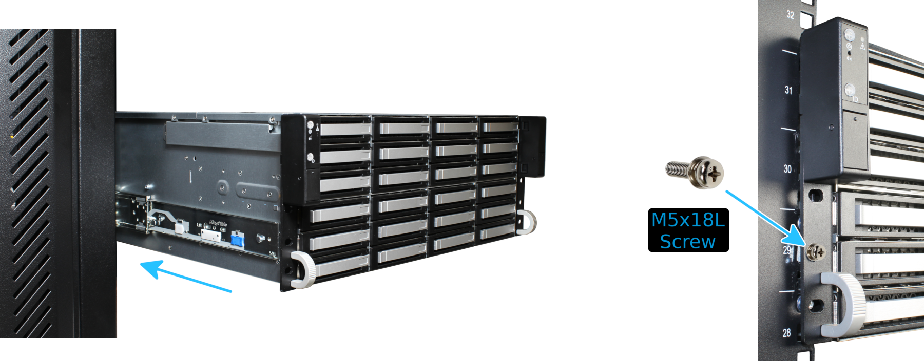
Anchor the unit in the rack on both sides with the M5x18L screws included in the rail kit.
16.2.3. Install Drive Trays
Drive trays are used to mount drives in the array. Drive trays are installed in drive bays in the chassis. Each drive bay in the chassis has two indicator LEDs to the right of the tray. The status LED is blue when the drive is active, and the fault LED is red if a fault has occurred.
Press the silver button on the drive tray to open the latch. Carefully slide the tray into a drive bay until the right side of the latch touches the metal front edge of the chassis, then gently swing the latch closed until it clicks into place.
16.2.4. Connect Expansion Shelves
Refer to the installation instructions included with expansion shelves for details on connecting them.
16.2.5. Connect Network Cables
Note: Network cables vary by configuration and are not included. Please contact iX Support with any questions.
Connect network cables to the Ethernet ports and Out-of-Band (OOB) management port before attempting to power on and configure the M-Series for the the first time.
16.2.6. Connect Power Cords
Do not plug the power cords into a power outlet yet. Connect a power cord to the back of one power supply. Place the cord into the plastic clamp and press the tab into the latch to lock it in place. Repeat the process for the second power supply and cord.
After both power cords have been connected to the M-Series, they can be plugged into power outlets. The system is configured to automatically power on when connected to a power outlet. This design ensures that the M-Series comes back on when power is restored after a power failure.
16.2.7. Install Bezel (Optional)
The included bezel is not required for operation.
16.2.8. Perform TrueNAS® Initial Software Configuration
The console displays the IP address of the TrueNAS® M-Series graphical web interface, 192.168.100.231 in this example:
The web user interface is at:

http://192.168.100.231
Enter the IP address into a browser on a computer on the same network to access the web user interface.
16.2.9. User Guide
The TrueNAS® User Guide with complete configuration instructions is available by clicking Guide in the TrueNAS® web interface or going directly to https://www.ixsystems.com/documentation/truenas/.
Copyright © 2019 iXsystems, Inc. All rights reserved.
All trademarks are the property of their respective owners.
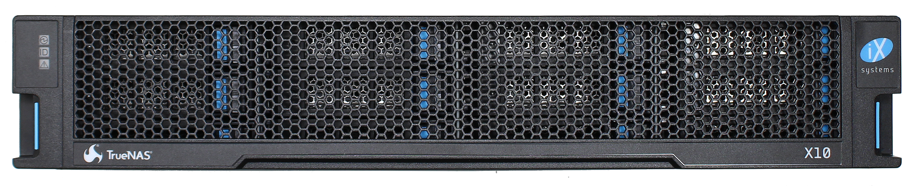
16.3. X-Series Unified Storage Array
The TrueNAS® X-Series Unified Storage Array is a 2U, 12-bay, hybrid unified data storage array.
Note
TrueNAS® units are carefully packed and shipped with
trusted carriers to arrive in perfect condition. If there is any
shipping damage or any parts are missing, please take photos and
contact iXsystems support immediately at
support@iXsystems.com or 1-855-GREP4-iX
(1-855-473-7449) or 1-408-943-4100.
Please locate and record the hardware serial numbers on the back or side of each chassis for easy reference.
Carefully unpack the shipping boxes and locate these components:
X-Series Unified Storage Array |
X-Series Bezel |
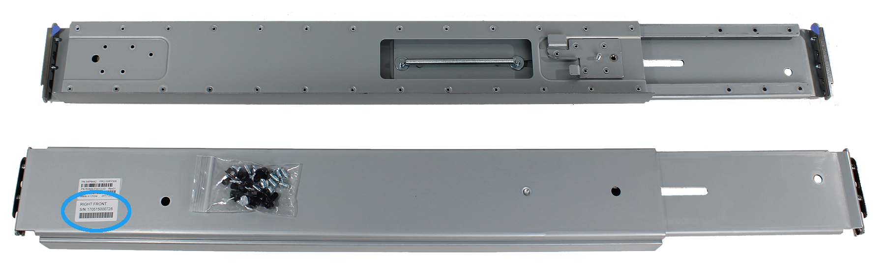
Set of rackmount rails. The rails have a specific front end, identified by a label visible on the left above. The front ends of the rails must be installed facing the front of the rack. |
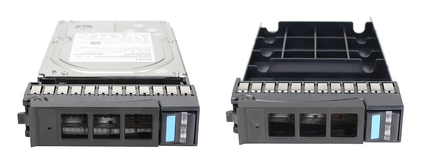
A total of 12 populated or empty “air baffle” drive trays. Trays must be installed in all bays to maintain proper airflow for cooling. Up to ten drive trays are packed in a cardboard tray. Additional drive trays are packed with the accessory kit. |
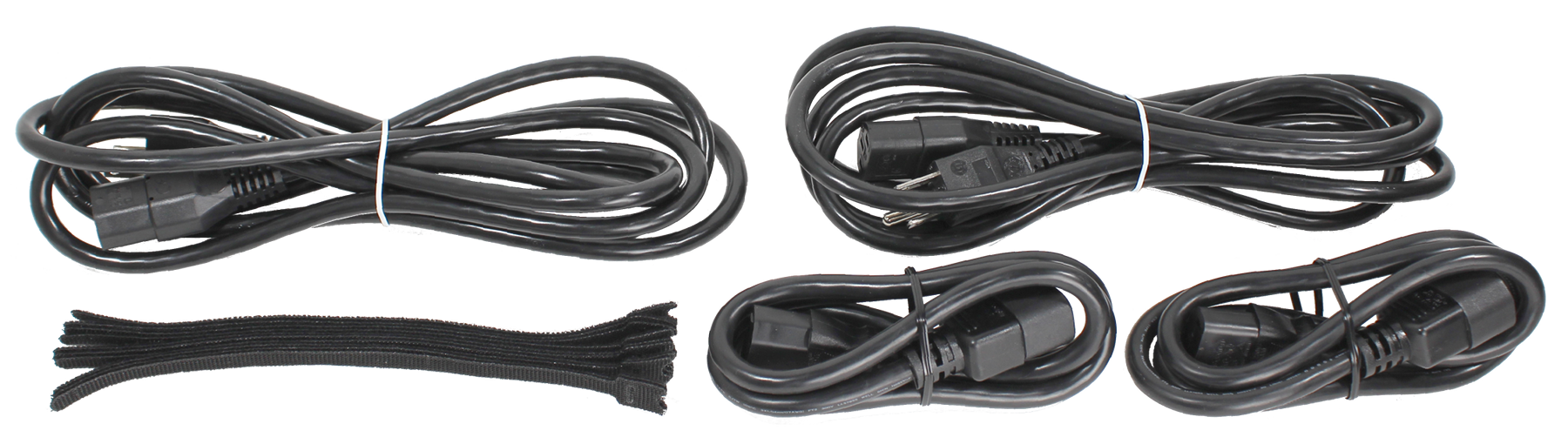
Accessory kit with 2 IEC C13 to NEMA 5-15P power cords, 2 IEC C14 to C14 cords, and velcro cable ties |
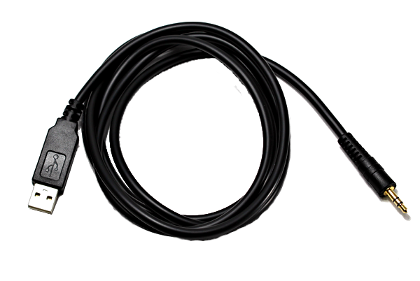
Black USB to 3.5mm, 3.3V serial cable and rail extenders for racks over 30” deep |
16.3.1. Become Familiar With the X-Series System
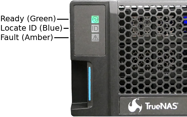
The X-Series has front panel indicators for power, locate ID, and fault. The fault indicator is on during the initial power-on self-test (POST) and turns off during normal operation. It turns on if the TrueNAS® software issues an alert. See the Alert section in the Additional Options chapter of the TrueNAS® User Guide.
The X-Series has one or two storage controllers in a side-by-side configuration.
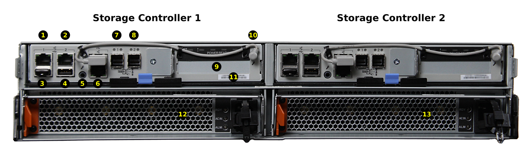
| 1,2: Gigabit Ethernet connectors | 7,8: HDmini SAS3 connectors 1 and 2 |
| 3: USB device (reserved, do not remove) | 9: PCIe x8 expansion port |
| 4: USB 2.0 connector | 10: System console port (reserved) |
| 5: Out-of-Band (OOB) serial port (3.5mm) | 11: MAC address label |
| 6: Out-of-Band Management Ethernet connector | 12, 13: Redundant power supplies |
16.3.2. Rail Kit Assembly
On racks that are 30 inches deep or less, proceed to rail spring installation below.
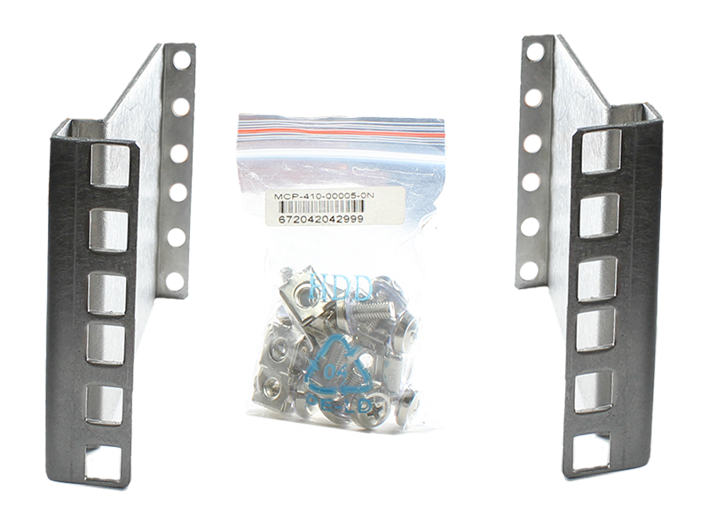
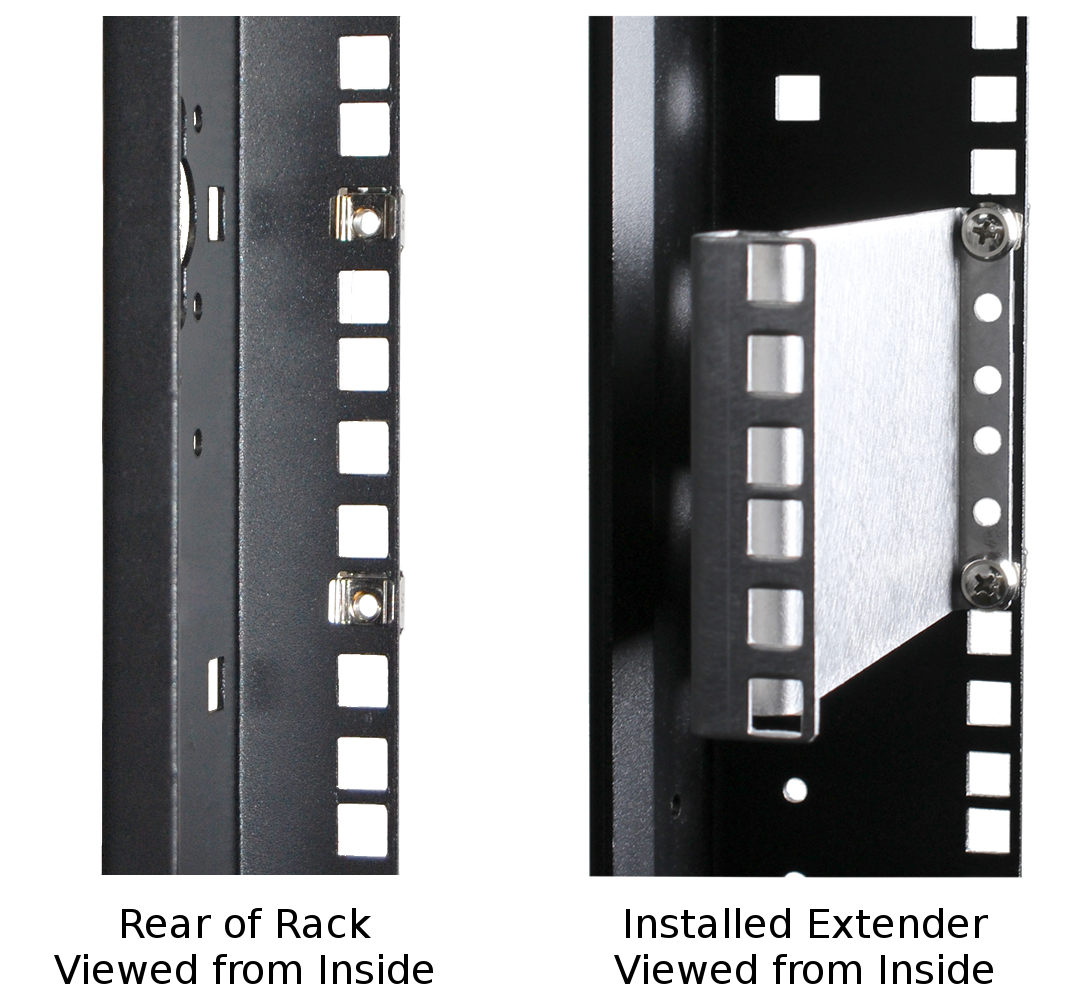
Racks from 31 to 36 inches deep require installation of the included rail extenders. For these deeper racks, install cage nuts on the outside rear of the rack. The tabs on the cage nuts must be horizontal as shown. Using the included bolts, install the rail extender inside the rear of the rack. Repeat the process for the second extender, which is a mirror image of the first.
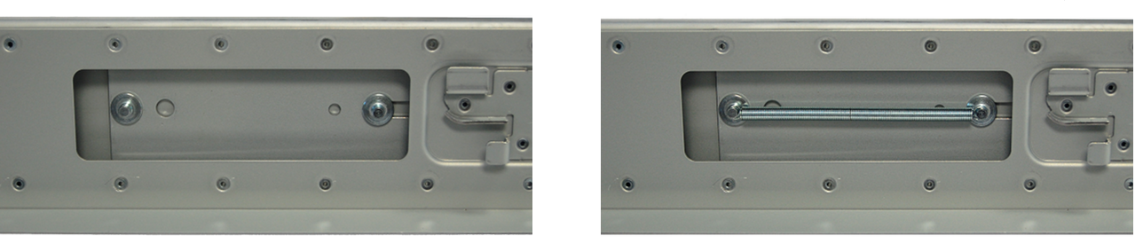
If not already present, install a spring on the silver posts in the side of each rail.
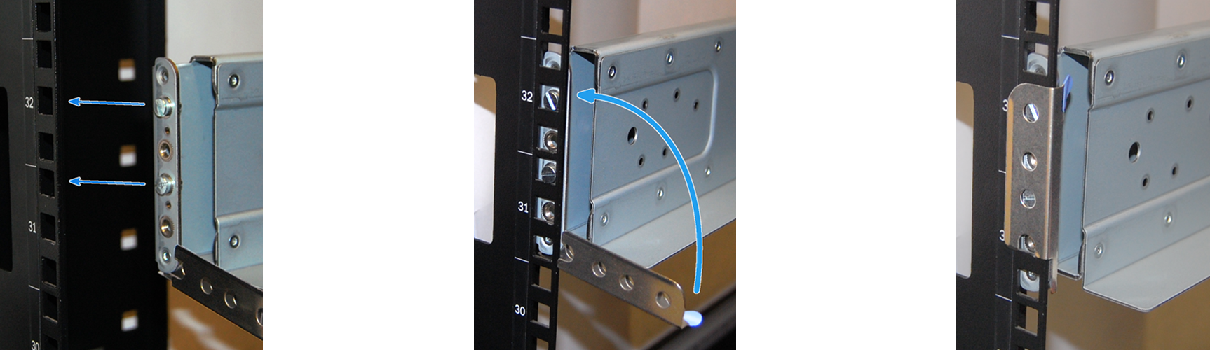
Open the clamp latches on the ends of each rail. Place the rail in the rack with the front end toward the front of the rack, aligning the pins on both ends of the rail with the mounting holes in the rack. Swing the clamp latch closed to hold the rail in place. Use two of the supplied screws to secure the back end of the rail in place. Repeat the process for the second rail.
Caution: Two people are required to safely lift the chassis for rack installation or removal. Do not install drives until after the chassis has been installed in the rack, and remove all drives before removing the chassis from the rack.
Carefully place the chassis onto the rails mounted in the rack. Push the chassis in until the ears are flush with the front of the rack. Use two of the supplied screws to secure each ear to the rack.
16.3.3. Install Drive Trays
Drive trays are used to mount drives in the chassis. Each drive tray has a status LED which is blue when active or amber if a fault has occurred.
A tray must be placed in each drive bay to maintain proper airflow for cooling. If fewer than twelve drives are connected, empty “air baffle” trays must be placed in the empty bays.
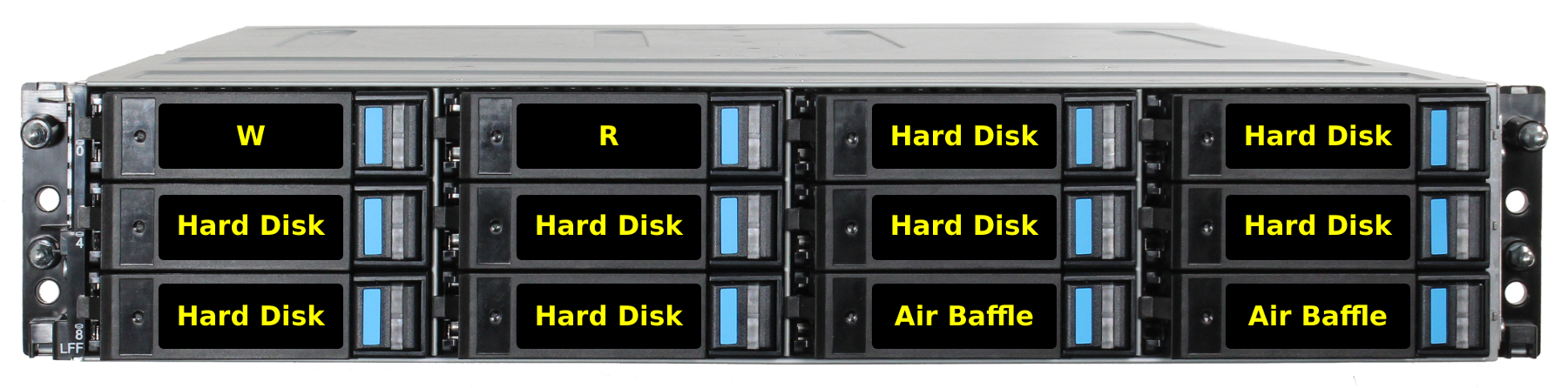
A standard drive tray installation order simplifies support and is strongly recommended:
- SSD drives for write cache (
W), if present - SSD drives for read cache (
R), if present - Hard drives or SSD drives for data storage
- Air baffle filler trays to fill any remaining empty bays
Install the first drive tray in the top left drive bay. Install the next drive tray to the right of the first. Install remaining drive trays to the right across the row. After a row is filled with drives, move down to the next row and start again with the left bay.
This example shows the proper order for a write cache (W)
SSD, a read cache (R) SSD, eight hard drives, and two empty
air baffle trays.
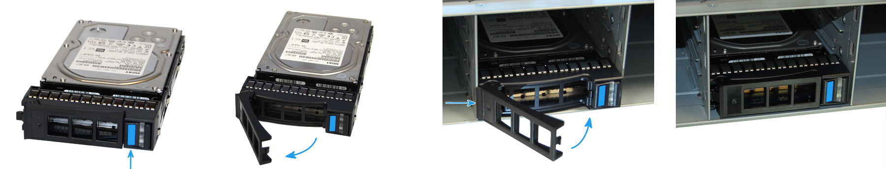
To load an individual drive tray into a bay, press the blue button to open the latch. Carefully slide the tray into a drive bay until the left side of the latch touches the metal front edge of the chassis, then gently swing the latch closed until it clicks into place.
16.3.4. Connect Expansion Shelves
Refer to the installation instructions included with expansion shelves for details on connecting them.
16.3.5. Connect Network Cables
Note: Network cables vary by configuration and are not included. Please contact iX Support with any questions.
Connect network cables to the Ethernet ports and Out-of-Band (OOB) management port before attempting to power on and configure the X-Series for the the first time.
The Out-of-Band (OOB) management port on the X-Series must be connected to a shielded Ethernet cable.
16.3.6. Connect Power Cords
If any TrueNAS® expansion shelves are connected to the X-Series, power them on first, then wait at least two minutes before connecting power cables to the X-Series.
Do not plug the power cords into a power outlet yet. Connect a power cord to the back of one power supply. Place the cord in the plastic clamp and press the tab into the latch to lock it in place. Repeat the process for the second power supply and cord.
After both power cords have been connected to the X-Series, they can be plugged into power outlets. The system is configured to automatically power on when connected to a power outlet. This design ensures that the X-Series comes back on when power is restored after a power failure.
If remote physical power disconnection is desired, the X-Series can be connected to a remotely-managed PDU (Power Distribution Unit).
16.3.7. Install Bezel (Optional)
The included bezel is not required for operation. If desired, install the bezel by aligning it with the pins on the bezel ears and pressing it into place.
16.3.8. Discover Out-of-Band Management IP Address
Several methods are available to determine the IP address currently assigned to the X-Series Out-of-Band management interface.
16.3.8.1. Preset
If the system was preconfigured by iXsystems, the Out-of-Band management interfaces have already been configured with the IP addresses requested by the user.
Otherwise, the Out-of-Band management IP addresses are set by default to static addresses:
Storage controller 1: 192.168.100.100, subnet mask 255.255.255.0
Storage controller 2 (if present): 192.168.100.101, subnet mask 255.255.255.0
16.3.8.2. DHCP
If the Out-of-Band management IP address has been configured to be assigned by DHCP, the IP address assigned by the DHCP server can be determined by checking the local DHCP server logs for the MAC addresses on the back panel of each X-Series storage controller, #11 on Figure 16.3.2.
The local DHCP server can also be configured to provide a fixed IP address for the X-Series Out-of-Band management by using the MAC address.
16.3.8.3. Serial Cable
The Out-of-Band management IP address can be identified or changed by temporarily connecting the black USB serial cable to the Out-of-Band serial port, #5 on Figure 16.3.2. Connect the USB end of the black cable to a laptop or desktop computer running serial terminal software.
Do not use the serial port for any purpose except checking the initial X-Series Out-of-Band management IP address or setting that address to be obtained by a different method. After use, disconnect the black USB serial cable from the X-Series.
Warning
The black USB serial cable is only for use with the Out-of-Band serial port on the X-Series. Do not attempt to use it with any other equipment.
16.3.8.3.1. Out-of-Band Serial Terminal Communication Settings
Serial Port Device Names
The name of the serial port varies with operating systems. These are
some typical examples: Windows: COM4,
macOS: /dev/tty.usbserialxynnn,
FreeBSD: /dev/cuaU0, Linux: /dev/ttyUSB0.
Serial Port Communication Parameters
Set the serial terminal program to use the appopriate port with these parameters: 38400 baud, 8 data bits, 1 stop bit, no parity, no flow control. Log in to the serial console with:
Username: sysadmin Password: superuser
The current Out-of-Band management IP address is displayed with:
ifconfig eth0 | grep 'inet addr'
      inet addr:10.20.1.227  Bcast:10.20.1.255  Mask:255.255.254.0
The current Out-of-Band network configuration settings are displayed with:
ipmitool -H 127.0.0.1 -U admin -P admin lan print
The Out-of-Band management system can be set to obtain an IP address from DHCP with:
ipmitool -H 127.0.0.1 -U admin -P admin lan set 1 ipsrc dhcp
The Out-of-Band management system can be set to use a static IP address and netmask. This example shows setting the IP address to 192.168.100.100 with a netmask of 255.255.255.0, and a default gateway of 192.168.100.1:
ipmitool -H 127.0.0.1 -U admin -P admin lan set 1 ipsrc static
ipmitool -H 127.0.0.1 -U admin -P admin lan set 1 ipaddr 192.168.100.10
ipmitool -H 127.0.0.1 -U admin -P admin lan set 1 netmask 255.255.255.0
ipmitool -H 127.0.0.1 -U admin -P admin lan set 1 defgw ipaddr 192.168.100.1
Log out of the Out-of-Band management system by typing exit
and pressing Enter.
After use, disconnect the black USB serial cable from the X-Series.
16.3.9. Connect to the X-Series Console
16.3.9.1. With IPMI
Note
The IPMItool remote management utility must be installed on the laptop or desktop computer used to manage the X-Series remotely, and that computer must have access to the same network as the X-Series. FreeBSD, macOS, and Linux have package systems which can be used to install IPMItool. For Windows, a simple option is to install IPMItool through Cygwin.
Warning
Only use IPMItool for remote IPMI management on the X-Series. Other IPMI utilities may not work correctly or even damage the X-Series system.
When the Out-of-Band management IP address has been determined, the X-Series console is accessible through IPMI. In this example, 192.168.100.100 is the IP address assigned to the Out-of-Band management interface:
ipmitool -I lanplus -H 192.168.100.100 -U admin -a sol activate
Enter admin for the password, and the X-Series console is connected.
Tip
When a Serial Over LAN connection is already in use,
SOL on another session is displayed when a laptop or
desktop computer attempts to connect. The Serial Over LAN system
can be reset from the remote laptop or desktop computer with:
ipmitool -H 192.168.100.100 -U admin bmc reset cold
Enter admin for the password, and the Serial Over LAN system is reset. Repeat the sol activate command above to connect.
The Serial Over LAN system can also be reset with the Out-of-Band serial port by attaching the black USB serial cable, connecting with a serial terminal program, and logging in as shown in Serial Cable. Then use
ifconfig eth0
to view the IP address of the eth0 network interface. Use the IP address, shown as eth0ipaddress in this example, in the reset command:
ipmitool -H eth0ipaddress -U admin bmc reset cold
Enter admin for the password, and the Serial Over LAN system is reset. Log out of the system with exit and disconnect the black USB serial cable from the X-Series system.
Tip
The Out-of-Band console password can be changed by attaching the black USB serial cable, connecting with a serial terminal program, and logging in as shown in Serial Cable. Then give this command to set the new password, shown as newpassword in this example:
ipmitool -H 127.0.0.1 -U admin -P admin user set password 2 newpassword
Log out of the system with exit and disconnect the black USB serial cable from the X-Series system.
Proceed to Using the X-Series Console.
16.3.9.2. With the Serial Cable
The X-Series console can be directly connected to a serial terminal program by temporarily disconnecting the gray serial cable from the system console serial port, #10 on Figure 16.3.2, and temporarily connecting the black USB serial cable to that port.
Connect the USB end of the black USB serial cable to a laptop or desktop computer running serial terminal software. See Out-of-Band Serial Terminal Communication Settings for the serial device name. Set the terminal software to:
115200 baud, 8 data bits, 1 stop bit, no parity, no flow control
Wait two minutes after the X-Series has been connected to power, then
press Enter to display the console menu. Find the message
starting with The web user interface is at: and write down
the IP address shown.
After viewing the X-Series console, disconnect the black USB serial
cable and reconnect the gray System Management cable
to the system serial console port, #10 on
Figure 16.3.2.
16.3.10. Using the X-Series Console
The X-Series console has two modes: SES (SCSI Enclosure Services) mode, and the standard x86 console mode.
If ESM A => is displayed, the X-Series is in SES mode.
Switch to the X86 console mode by typing these characters:
$%^0
Press Enter twice after typing the characters. The normal x86
console is displayed.
To switch back to the SES console, type these characters:
$%^2
16.3.11. Perform TrueNAS® Initial Software Configuration
The console displays the IP address of the TrueNAS® X-Series graphical web interface, 192.168.100.231 in this example:
The web user interface is at:

http://192.168.100.231
Enter the IP address into a browser on a computer on the same network to access the web user interface.
16.3.12. User Guide
The TrueNAS® User Guide with complete configuration instructions is available by clicking Guide in the TrueNAS® web interface or going directly to https://www.ixsystems.com/documentation/truenas/.
Copyright © 2019 iXsystems, Inc. All rights reserved.
All trademarks are the property of their respective owners.
16.4. ES12 Expansion Shelf
The TrueNAS® ES12 is a 2U, 12-bay, SAS3 (12 Gb/s) expansion shelf with dual expansion controllers and redundant power supplies.
Note
TrueNAS® units are carefully packed and shipped with
trusted carriers to arrive in perfect condition. If there is any
shipping damage or any parts are missing, please take photos and
contact iXsystems support immediately at
support@iXsystems.com or 1-855-GREP4-iX
(1-855-473-7449) or 1-408-943-4100.
Please locate and record the hardware serial numbers on the back or side of each chassis for easy reference.
Carefully unpack the shipping boxes and locate these components:
|
ES12 Expansion Shelf |
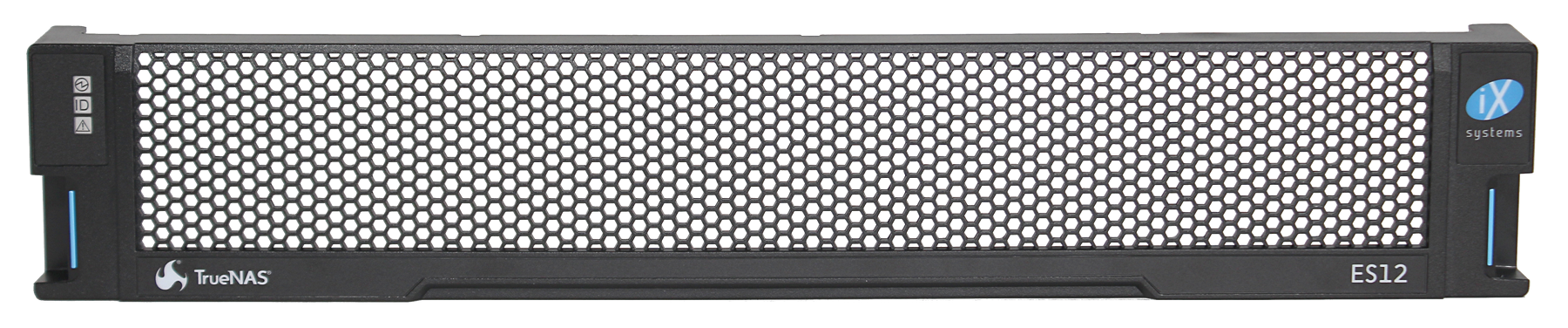
ES12 Bezel |
|
Set of rackmount rails. The rails have a specific front end, identified by a label visible on the left above. The front ends of the rails must be installed facing the front of the rack. |
A total of 12 populated or empty “air baffle” drive trays. Trays must be installed in all bays to maintain proper airflow for cooling. Up to ten drive trays are packed in a cardboard tray. Additional drive trays are packed with the accessory kit. |
|
Accessory kit with 2 IEC C13 to NEMA 5-15P power cords, 2 IEC C14 to C14 cords, and a set of velcro cable ties |
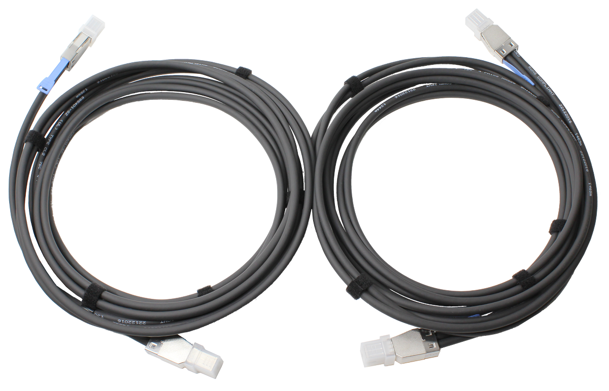
Two 3-meter Mini SAS HD to Mini SAS HD cables |
16.4.1. Become Familiar With the ES12 System
The ES12 has front panel indicators for power, locate ID, and fault. The fault indicator is on during the initial power-on self-test (POST) and turns off during normal operation. It turns on if the TrueNAS® software issues an alert. See the Alert section in the Additional Options chapter of the TrueNAS® User Guide.
The ES12 has two expansion controllers in a side-by-side configuration:
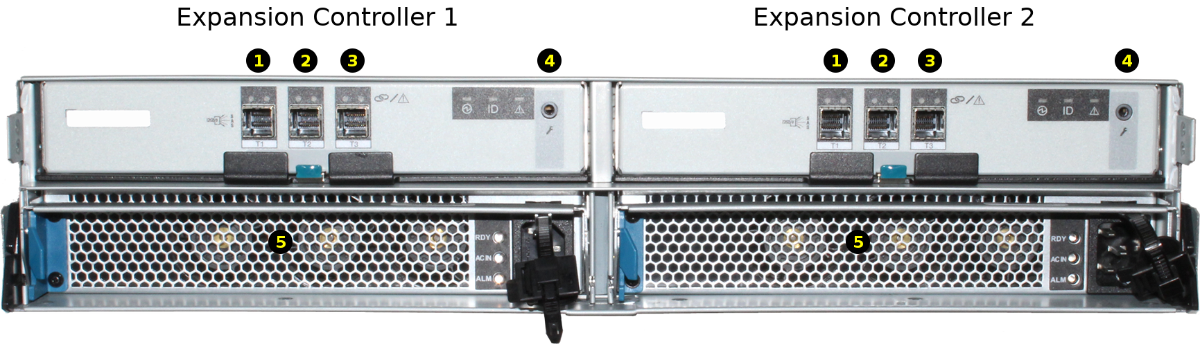
| 1-3: HD Mini SAS3 connectors (T1-T3) |
| 4: Debug port (TrueNAS® internal use only) |
| 5: Redundant power supplies |
16.4.2. Rail Kit Assembly
On racks that are 30 inches deep or less, proceed to rail spring installation below.
Racks from 31 to 36 inches deep require installation of the included rail extenders. For these deeper racks, install cage nuts on the outside rear of the rack. The tabs on the cage nuts must be horizontal as shown. Using the included bolts, install the rail extender inside the rear of the rack. Repeat the process for the second extender, which is a mirror image of the first.
If not already present, install a spring on the silver posts in the side of each rail.
Open the clamp latches on the ends of each rail. Place the rail in the rack with the front end toward the front of the rack, aligning the pins on both ends of the rail with the mounting holes in the rack. Swing the clamp latch closed to hold the rail in place. Use two of the supplied screws to secure the back end of the rail in place. Repeat the process for the second rail.
Caution: Two people are required to safely lift the chassis for rack installation or removal. Do not install drives until after the chassis has been installed in the rack, and remove all drives before removing the chassis from the rack.
Carefully place the chassis onto the rails mounted in the rack. Push the chassis in until the ears are flush with the front of the rack. Use two of the supplied screws to secure each ear to the rack.
16.4.3. Install Drive Trays
Drive trays are used to mount drives in the chassis. Each drive tray has a status LED which is blue when active or amber if a fault has occurred.
A tray must be placed in each drive bay to maintain proper airflow for cooling. If fewer than twelve drives are connected, empty “air baffle” trays must be placed in the empty bays.
A standard drive tray installation order simplifies support and is strongly recommended:
- SSD drives for write cache (
W), if present - SSD drives for read cache (
R), if present - Hard drives or SSD drives for data storage
- Air baffle filler trays to fill any remaining empty bays
Install the first drive tray in the top left drive bay. Install the next drive tray to the right of the first. Install remaining drive trays to the right across the row. After a row is filled with drives, move down to the next row and start again with the left bay.
This example shows the proper order for a write cache (W)
SSD, a read cache (R) SSD, eight hard drives, and two empty
air baffle trays.
To load an individual drive tray into a bay, press the blue button to open the latch. Carefully slide the tray into a drive bay until the left side of the latch touches the metal front edge of the chassis, then gently swing the latch closed until it clicks into place.
16.4.4. Connect Power Cords
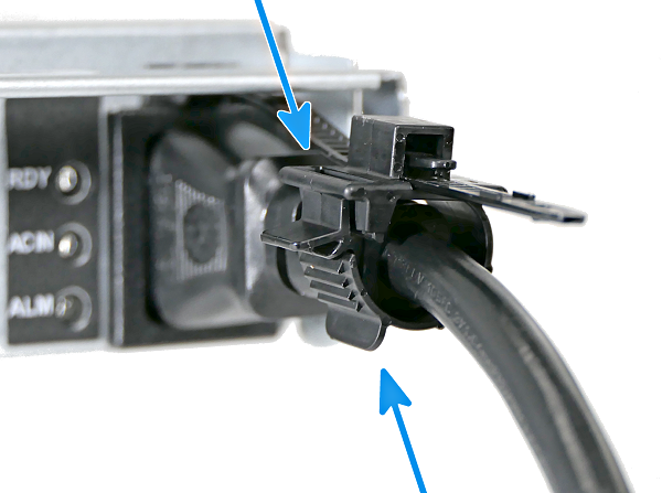
Do not plug the power cords into a power outlet yet. Connect a power cord to the back of one power supply. Place the cord in the plastic clamp and press the tab into the latch to lock it in place. Repeat the process for the second power supply and cord.
16.4.5. Connect SAS Cables
Plug the ES12 power cords into power outlets. Wait two minutes for the drives to start.
The ES12 is compatible with several TrueNAS® systems. Typical SAS cable connections for one or two ES12 expansion shelves to TrueNAS® High Availability (HA) systems are shown here. When a TrueNAS® unit with only a single storage controller is used, only cables #1 and #3 are connected.
X-Series
M40
M50
Connect SAS cables to the ES12 T slots. These are the typical SAS connections for one or two ES12 expansion shelves connecting to a High Availability (HA) TrueNAS® system with two storage controllers. When a TrueNAS® unit with only a single storage controller is used, only cables #1 and #3 are connected.
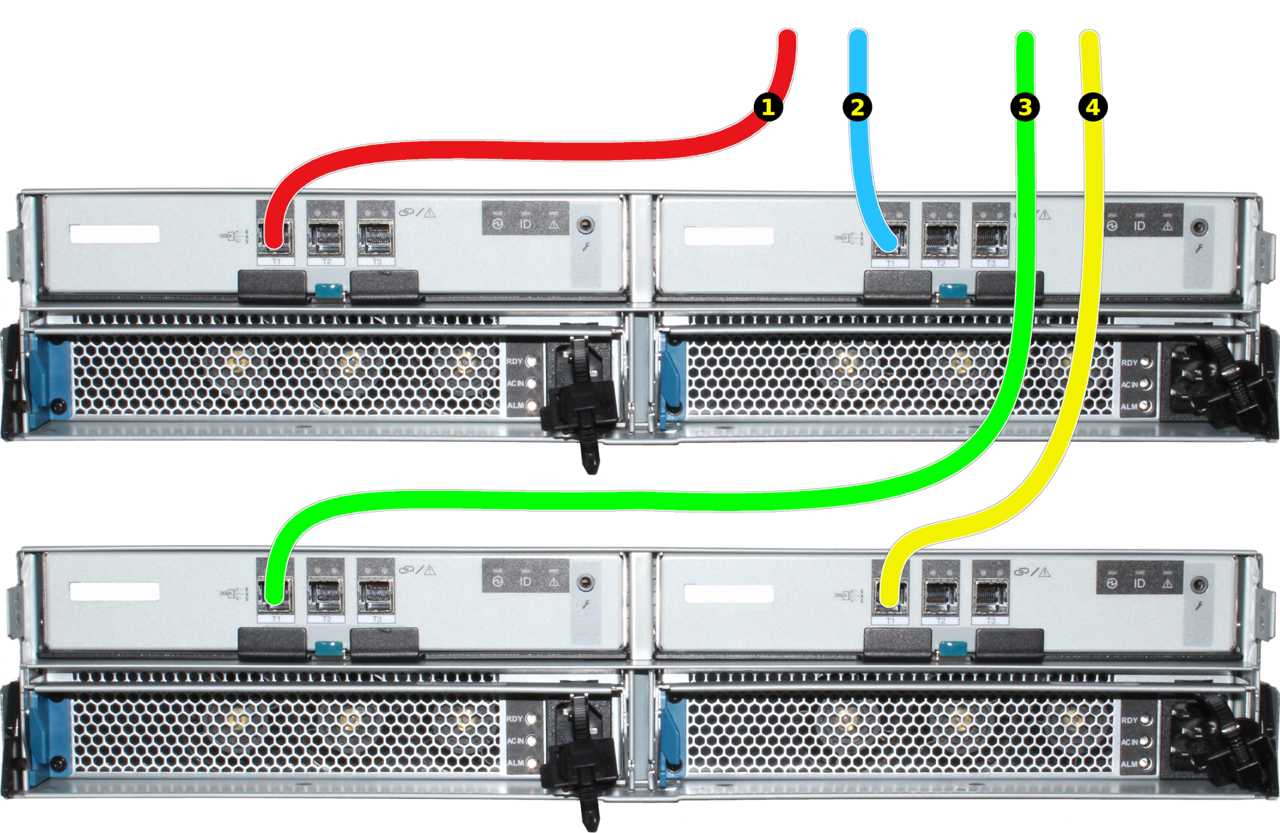
- Connect cable #1 to the ES12 expansion controller 1 T1 slot.
- Connect cable #2 to the ES12 expansion controller 2 T1 slot.
If a second ES12 is present:
- Connect cable #3 to the second ES12 expansion controller 1 T1 slot.
- Connect cable #4 to the second ES12 expansion controller 2 T1 slot.
16.4.6. Install Bezel (Optional)
The included bezel is not required for operation. If desired, install the bezel by aligning it with the pins on the bezel ears and pressing it into place.
16.4.7. User Guide
The TrueNAS® User Guide with complete configuration instructions is available by clicking Guide in the TrueNAS® web interface or going directly to https://www.ixsystems.com/documentation/truenas/.
Copyright © 2019 iXsystems, Inc. All rights reserved.
All trademarks are the property of their respective owners.
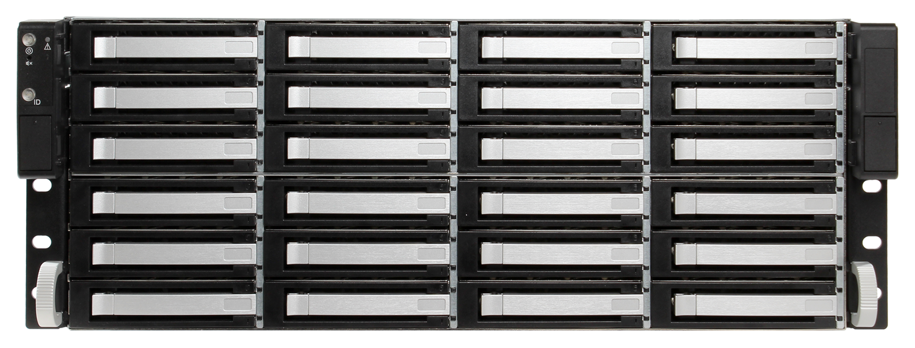
16.5. ES24 Expansion Shelf
The TrueNAS® ES24 is a 4U, 24-bay, SAS3 (12 Gb/s) expansion shelf with dual expansion controllers and redundant power supplies.
Note
TrueNAS® units are carefully packed and shipped with
trusted carriers to arrive in perfect condition. If there is any
shipping damage or any parts are missing, please take photos and
contact iXsystems support immediately at
support@iXsystems.com or 1-855-GREP4-iX
(1-855-473-7449) or 1-408-943-4100.
Please locate and record the hardware serial numbers on the back or side of each chassis for easy reference.
Carefully unpack the shipping boxes and locate these components:
ES24 Expansion Shelf |
|
Set of rackmount rails |
Up to 24 drive trays populated with drives |
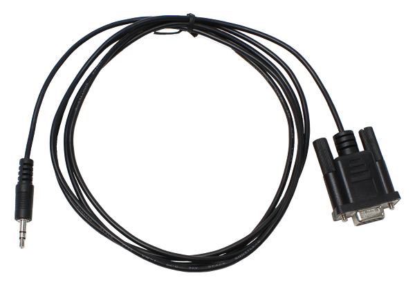
Two 3-meter Mini SAS HD to Mini SAS HD cables and one serial cable |
Two 2 IEC C13 to NEMA 5-15P power cords |
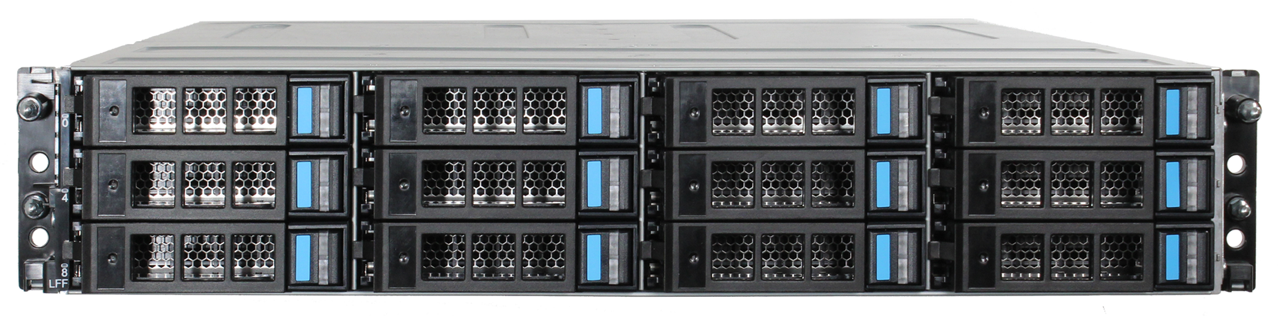
16.5.1. Become Familiar With the ES24
The ES24 has front panel buttons for power and alarm mute, and indicators for power, locate ID, and fault. The fault indicator is on during the initial power-on self-test (POST) or when the TrueNAS® software has issued an alert. See the Alert section in the Additional Options chapter of the TrueNAS® User Guide.
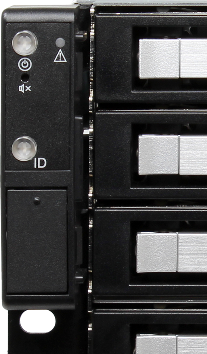
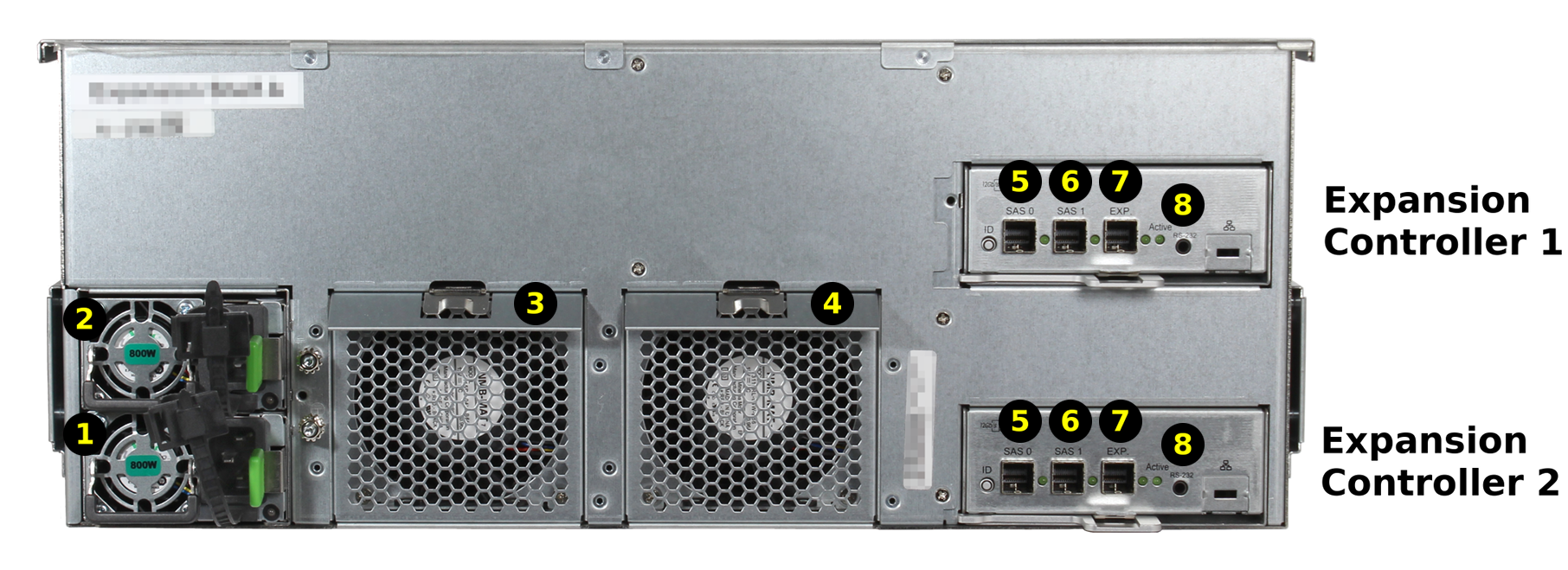
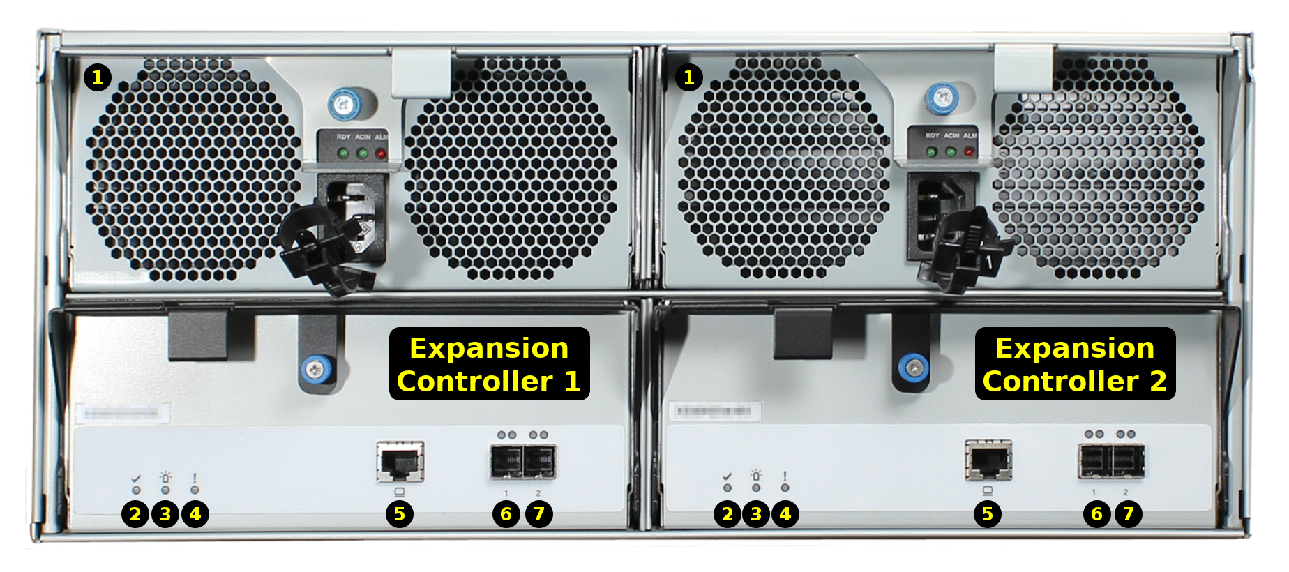
Fig. 16.5.2 Back Panel
The ES24 has two expansion controllers in an over/under configuration. The connectors and features on each controller are:
| 1-2: Redundant power supplies |
| 3-4: Fans |
| 5-7: HD Mini SAS3 connectors |
| 8: Serial port |
16.5.2. ES24 and M-Series Rail Kit Assembly
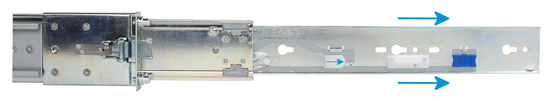
16.5.2.1. Remove Cabinet Rails from Rack Rails
Extend the cabinet rail until it stops. To remove the cabinet rail, press the white release tab to the right while pulling the cabinet rail.
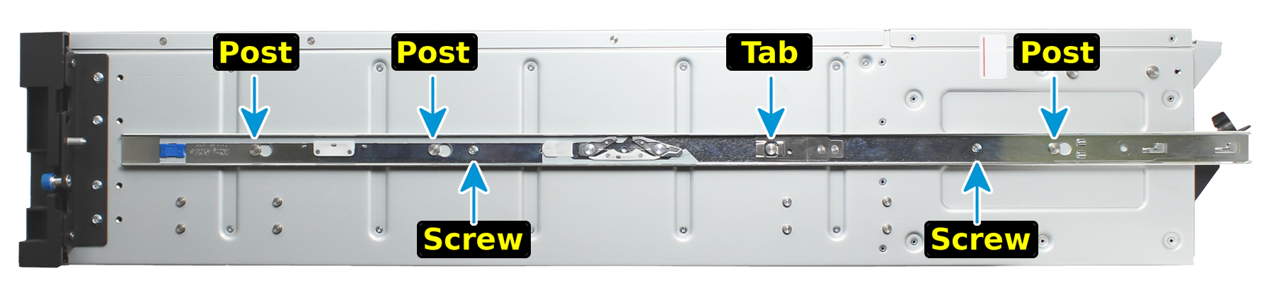
16.5.2.2. Mount Cabinet Rails
The cabinet rails are mounted on both sides of the system cabinet. Align the cabinet rail keyholes with the three posts (ES24) or four posts (M-Series) on the side of the chassis and slide the rail until the post is secured in the keyhole slot of the rail.
Align the rail hole with the screw hole and secure the rail with one M4x4L screw from the rail kit. Repeat this process to mount and secure the second cabinet rail on the other side.
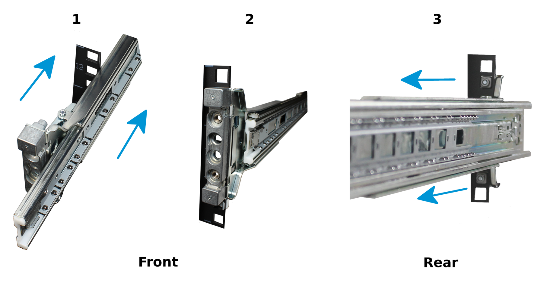
16.5.2.3. Mount the Rack Rails
Place the rail in the rack with the front end toward the front of the rack, aligning the pins with the mounting holes in the front of the rack. Push the pins into the holes until the latch clicks.
For the rear end of the rail, align the pins with the mounting holes on the rear rack. Pull the white latch toward the rear until the pins click in place. Repeat this process for the second rear rail.
16.5.2.4. Mount the Unit in the Rack
Caution: Two people are required to safely lift the chassis for rack installation or removal. Do not install drives until after the chassis has been installed in the rack, and remove all drives before removing the chassis from the rack.
Pull the front rack rail forward until it stops. Align the cabinet rail with the inside of the front rack rail and slide the cabinet rail forward until it is fully seated inside the rack rail. Repeat the process for the second rail.
When both cabinet rails are secured in the rack rails, gently push the chassis until it stops halfway in. Slide the blue release tabs on both cabinet rails toward the front of the system while pushing the unit in. Push the chassis into the rack until it is flush with the front of the rack.
Anchor the unit in the rack on both sides with the M5x18L screws included in the rail kit.
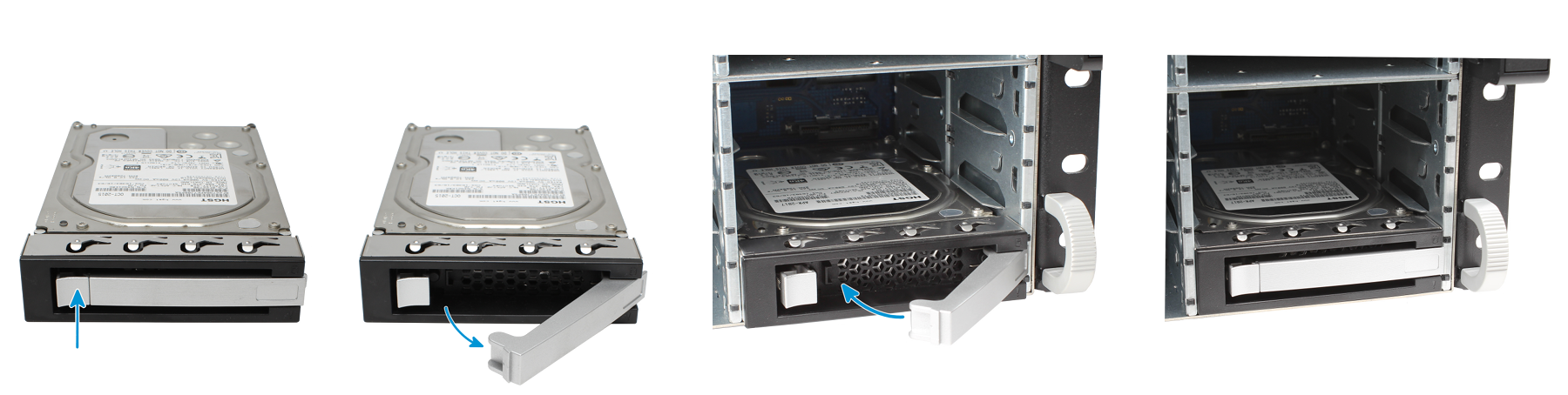
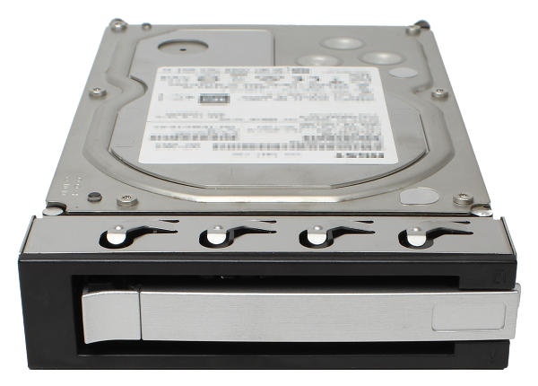
16.5.3. Install Drive Trays
Drive trays are used to mount drives in the array. Drive trays are installed in drive bays in the chassis. Each drive bay in the chassis has two indicator LEDs to the right of the tray. The status LED is blue when the drive is active, and the fault LED is red if a fault has occurred.
Press the silver button on the drive tray to open the latch. Carefully slide the tray into a drive bay until the right side of the latch touches the metal front edge of the chassis, then gently swing the latch closed until it clicks into place.
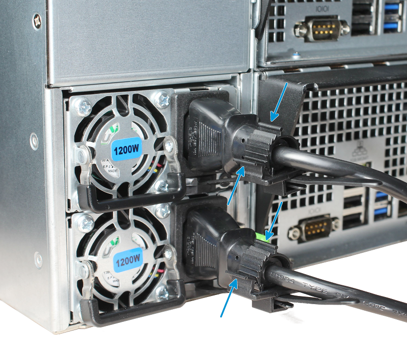
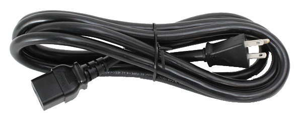
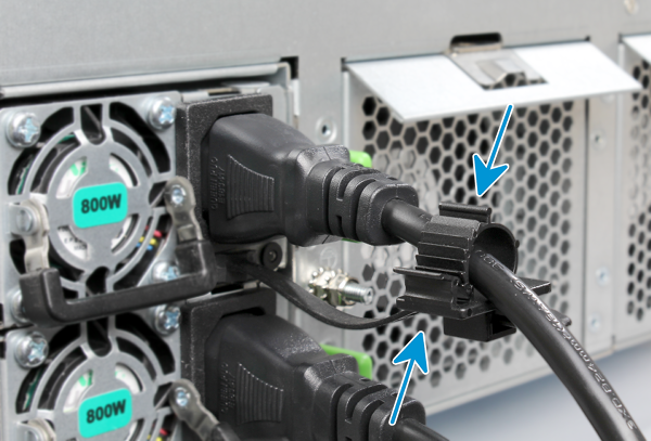
16.5.4. Connect Power Cords
Do not plug the power cords into a power outlet yet. Connect a power cord to the back of one power supply. Place the cord into the plastic clamp and press the tab into the latch to lock it in place. Repeat the process for the second power supply and cord.
16.5.5. Connect The Expansion Shelf
Plug the ES24 power cords into power outlets. Wait two minutes for the drives to start.
If the TrueNAS® system is on, it can remain on while the expansion shelf is connected.
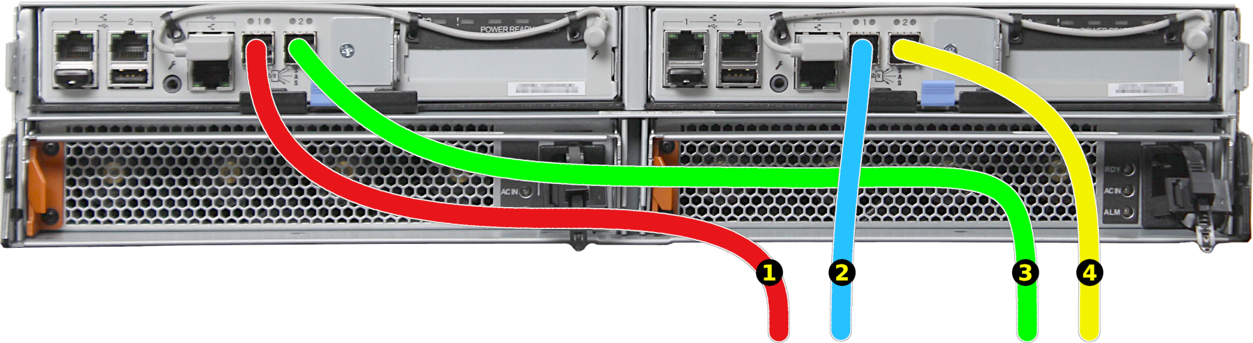
The ES24 is compatible with several TrueNAS® systems. Typical SAS cable connections for connecting one or two ES24 units to TrueNAS® High Availability (HA) systems are shown here. When a TrueNAS® unit with only a single storage controller is used, only cables #1 and #3 are connected.
X-Series
M40
M50
The SAS cables from the TrueNAS® system connect to these ports on the ES24:
- Connect cable #1 to the first ES24, expansion controller 1 SAS 0 port.
- Connect cable #2 to the first ES24, expansion controller 2 SAS 0 port.
If a second ES24 is present:
- Connect cable #3 to the second ES24, expansion controller 1 SAS 0 port.
- Connect cable #4 to the second ES24, expansion controller 2 SAS 0 port.
16.5.6. User Guide
The TrueNAS® User Guide with complete configuration instructions is available by clicking Guide in the TrueNAS® web interface or going directly to https://www.ixsystems.com/documentation/truenas/.
Copyright © 2019 iXsystems, Inc. All rights reserved.
All trademarks are the property of their respective owners.
Note
The ES60 replaces the previous E60 expansion shelf. The E60 reached end of life (EOL) on May 17, 2017, but will continue to be supported until May 17, 2022.
16.6. ES60 Expansion Shelf
The TrueNAS® ES60 Expansion Shelf is a 4U, 60-bay storage expansion unit designed specifically for use with the TrueNAS® Unified Storage Array.
Note
TrueNAS® units are carefully packed and shipped with
trusted carriers to arrive in perfect condition. If there is any
shipping damage or any parts are missing, please take photos and
contact iXsystems support immediately at
support@iXsystems.com or 1-855-GREP4-iX
(1-855-473-7449) or 1-408-943-4100.
Please locate and record the hardware serial numbers on the back or side of each chassis for easy reference.
Carefully unpack the shipping boxes and locate these components:
ES60 Expansion Shelf |
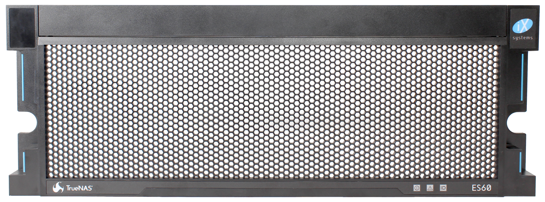
ES60 Bezel |
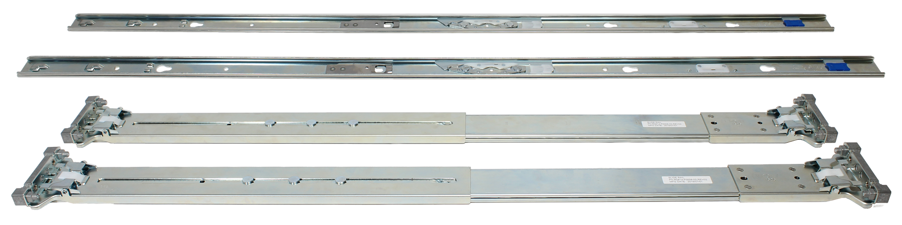
Rail kit with mounting hardware |
Up to 60 drive trays with installed hard drives (shipped separately from the ES60) |
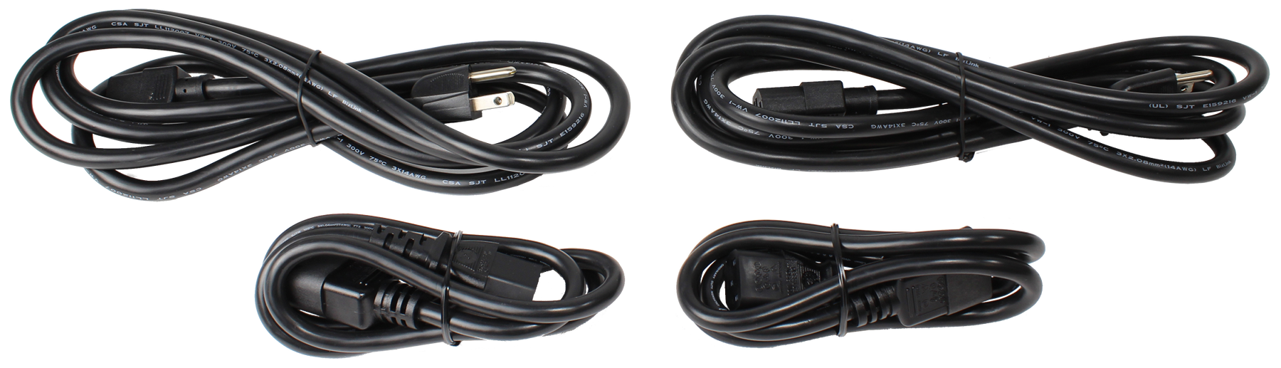
Two IEC C13 to NEMA 5-15P power cords, two IEC C14 to C14 power cords |
Two 3-meter Mini SAS HD to Mini SAS HD cables |
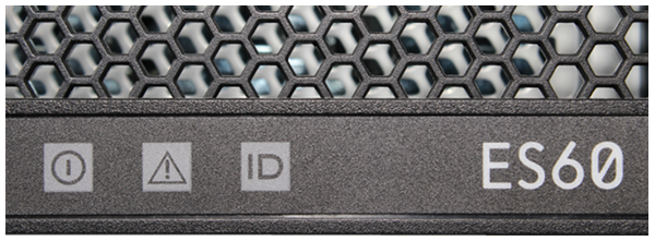
16.6.1. Become Familiar With the ES60
Indicators on the front panel show power, fault, and locate ID. The fault indicator is on during the initial power-on self-test (POST) or when the TrueNAS® software has issued an alert. See the Alert section in the Additional Options chapter of the TrueNAS® User Guide..
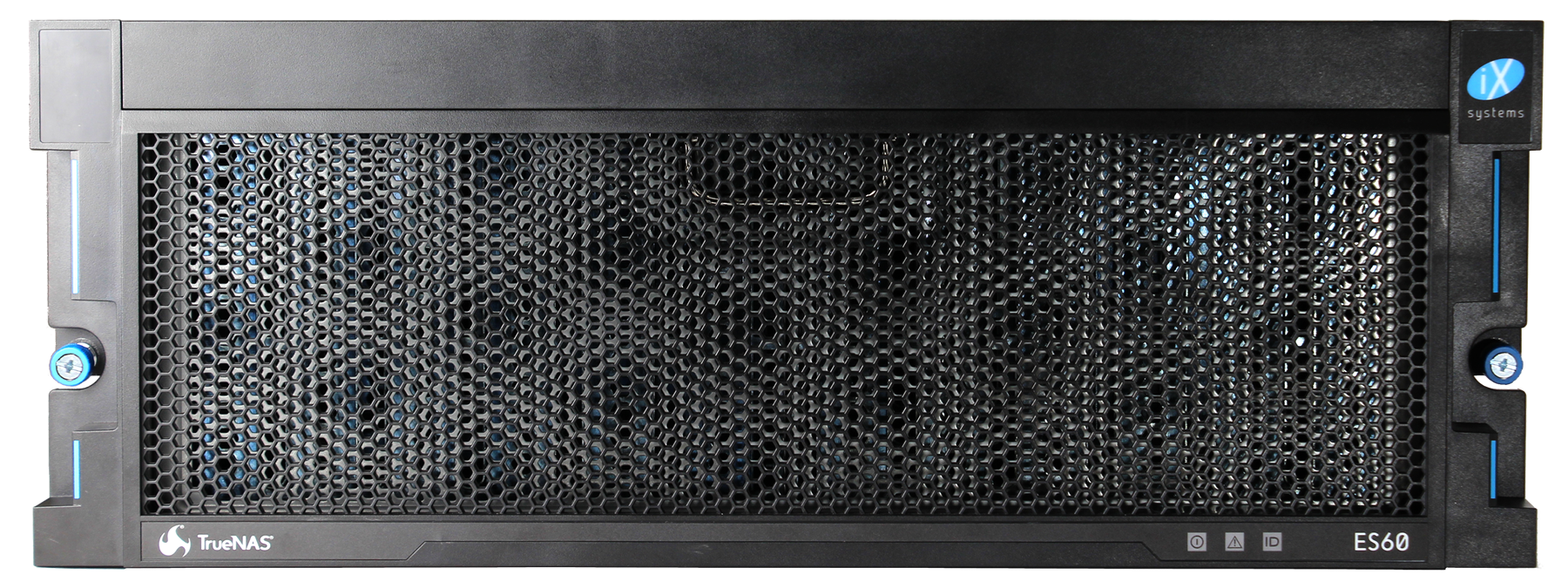
Front panel indicators:
The ES60 has two expansion controllers in a side-by-side configuration.
| 1: Power supply | 4: Locate ID |
| 2: Power indicator | 5: Management port (not used) |
| 3: Alarm indicator | 6,7: HD Mini SAS3 connectors |
16.6.2. Rail Kit Assembly
16.6.2.1. Separate Cabinet Rails from Rack Rails
Each rack rail includes an inner cabinet rail that must be removed. Extend the cabinet rail until the white release tab is exposed.
Press the white release tab to the right while pulling the cabinet rail to remove it. Repeat this process for the second rail.
16.6.2.2. Mount Cabinet Rails
The cabinet rails are mounted on each side of the system. Align the cabinet rail keyholes with the posts on the side of the chassis. Slide the rail toward the rear of the system until the metal tab clicks and secures the rail in place. Repeat this process on the other side.
16.6.2.3. Mount Rack Rails
Install four cage nuts in the rack, two where the rails attach to the front of the rack, and two at the rear. Place the rail in the rack with the front end toward the front of the rack and rear toward the back of the rack, aligning the pins on both ends of the rail with the mounting holes in the rack. Push the pins into the rack holes until they lock in place.
16.6.3. Mount Unit in the Rack
Caution: Two people are required to safely lift the chassis for rack installation or removal. Do not install drives until after the chassis has been installed in the rack, and remove all drives before removing the chassis from the rack.
Slide the front rack rail forward to meet the rear of the cabinet rails. Align the cabinet rail with the inside of the front rack rail and slide the cabinet rail forward until it is fully seated inside the rack rail. Repeat the process for the second rail.
When both cabinet rails are secured inside the rack rails, carefully slide the chassis until the ears are flush with the front of the rack. Tighten both blue screws on the ears of the chassis to secure the unit in the rack.
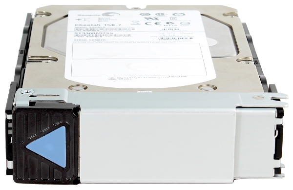
16.6.4. Drive Tray Installation
Do not install the drives until the chassis has been installed in the rack.
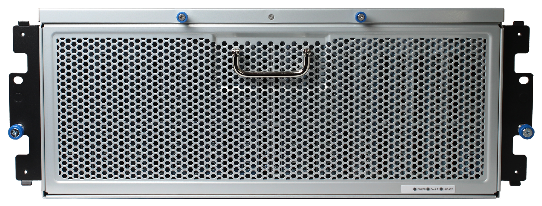
16.6.4.1. Remove Top Cover
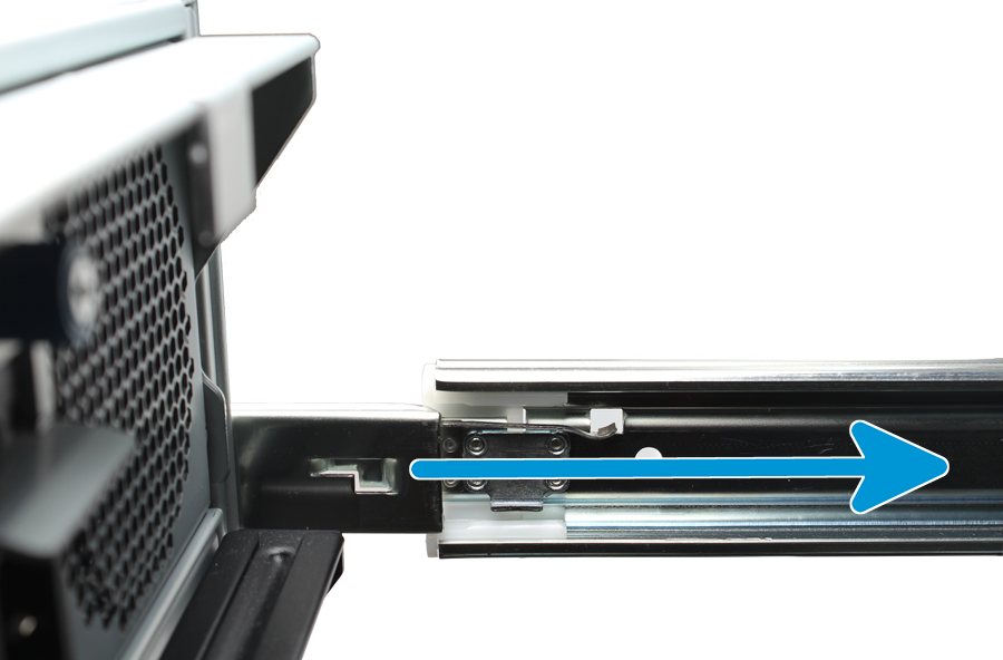
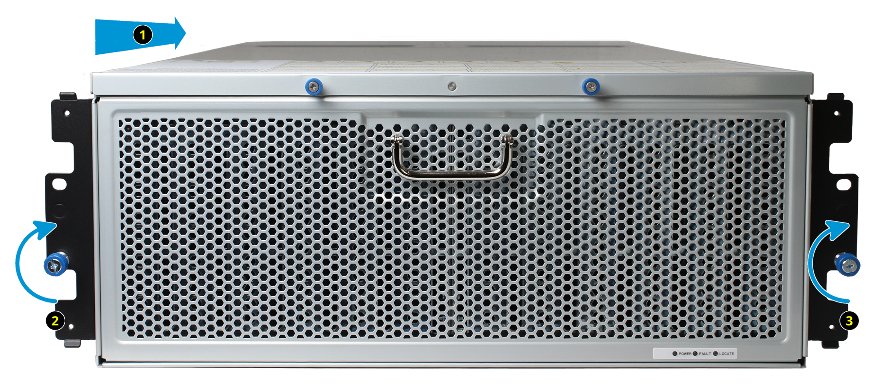
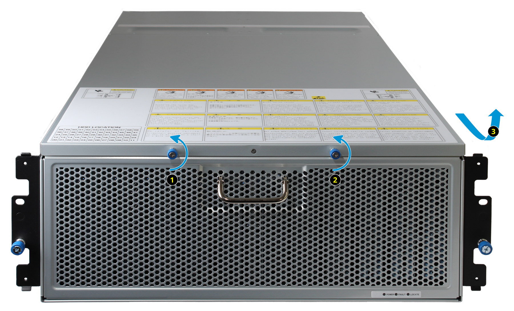
Slide the unit out on the rails. Turn the blue screws counterclockwise to unlock the top cover. Slide the top cover toward the front of the system, then lift to remove it.
16.6.4.2. Install Drive Trays
Drive trays are used to mount drives in the array.
A standard drive tray installation order simplifies support and is strongly recommended:
- SSD drives for SLOG, if present
- SSD drives for L2ARC, if present
- Hard drives or SSD drives for data storage
Install the first drive tray in the front left drive bay. Install the next drive tray to the right of the first. Install remaining drive trays to the right across the row. After a row is filled with drives, move back to the next row and start again with the left bay. A label on the front left of the lid identifies the preferred order of drive connection.
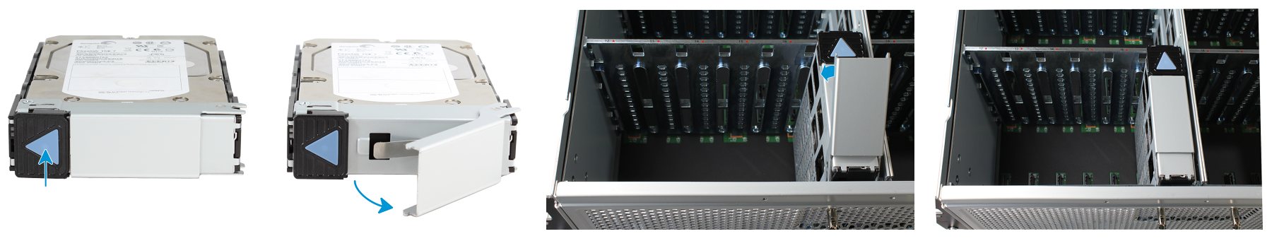
Press the blue button to open the latch. Lower the drive tray into a drive bay until the latch begins to move into place. Push the latch the rest of the way until it locks into place.
16.6.5. ES60 Cable Management Arm
The included cable management arm (CMA) is not required for operation. If desired, the CMA can be used to help organize the ES60 power and data cables.
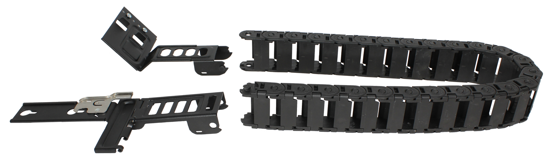
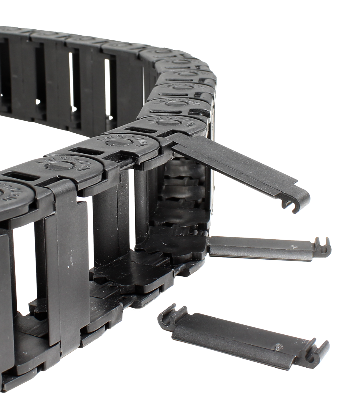
The tabs along the side of the flex housing can be unclipped from the top, the bottom, or removed entirely.
16.6.5.1. Install the Cable Management Arm
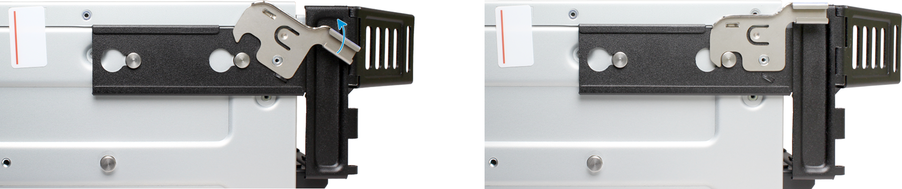
Locate the two posts on the left rear side of the ES60. Align the holes on the CMA chassis bracket with the posts on the chassis. Slide the cable management arm forward and pull the lever on the latch upward to lock the bracket into place.
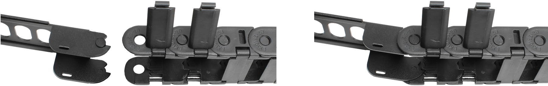
Locate the end of the flex housing with exposed pins. Unclip and open the two tabs closest to the end, allowing the flex housing to compress enough to fit into the bracket holes. Press the flex housing firmly into the bracket until the pins seat in the holes.
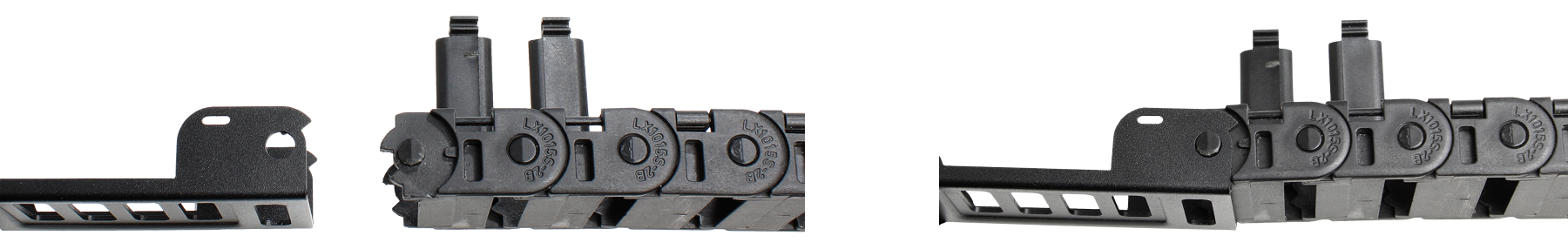
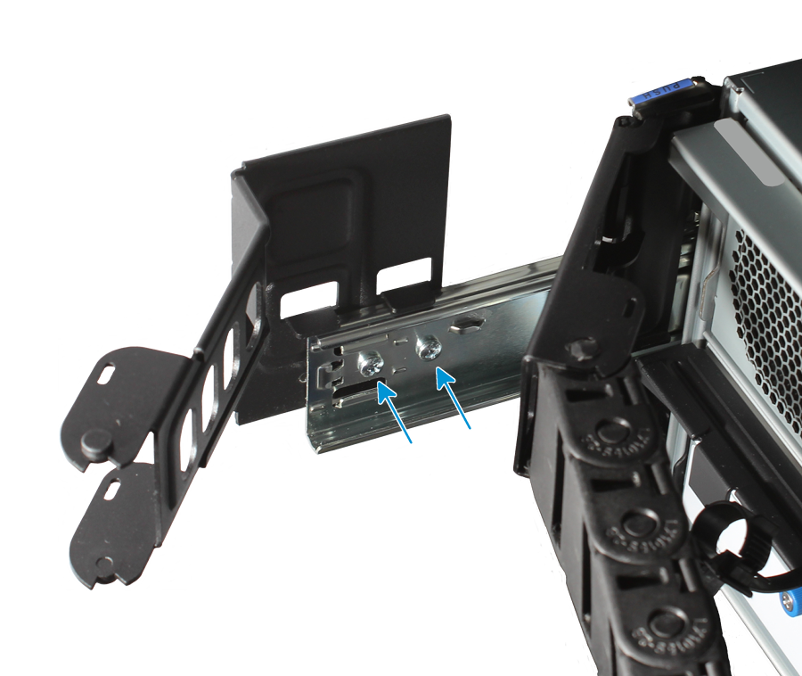
Remove the two screws already attached to the side of the CMA rail bracket. Align the screw holes with the holes in the rear of the left cabinet rail and attach the bracket to the rail with the screws.
Locate the end of the flex housing with exposed holes. Unclip and open the two tabs closest to the end, allowing the flex housing to expand enough to fit over the bracket pins. Press the flex housing firmly into the bracket until the holes seat on the pins.
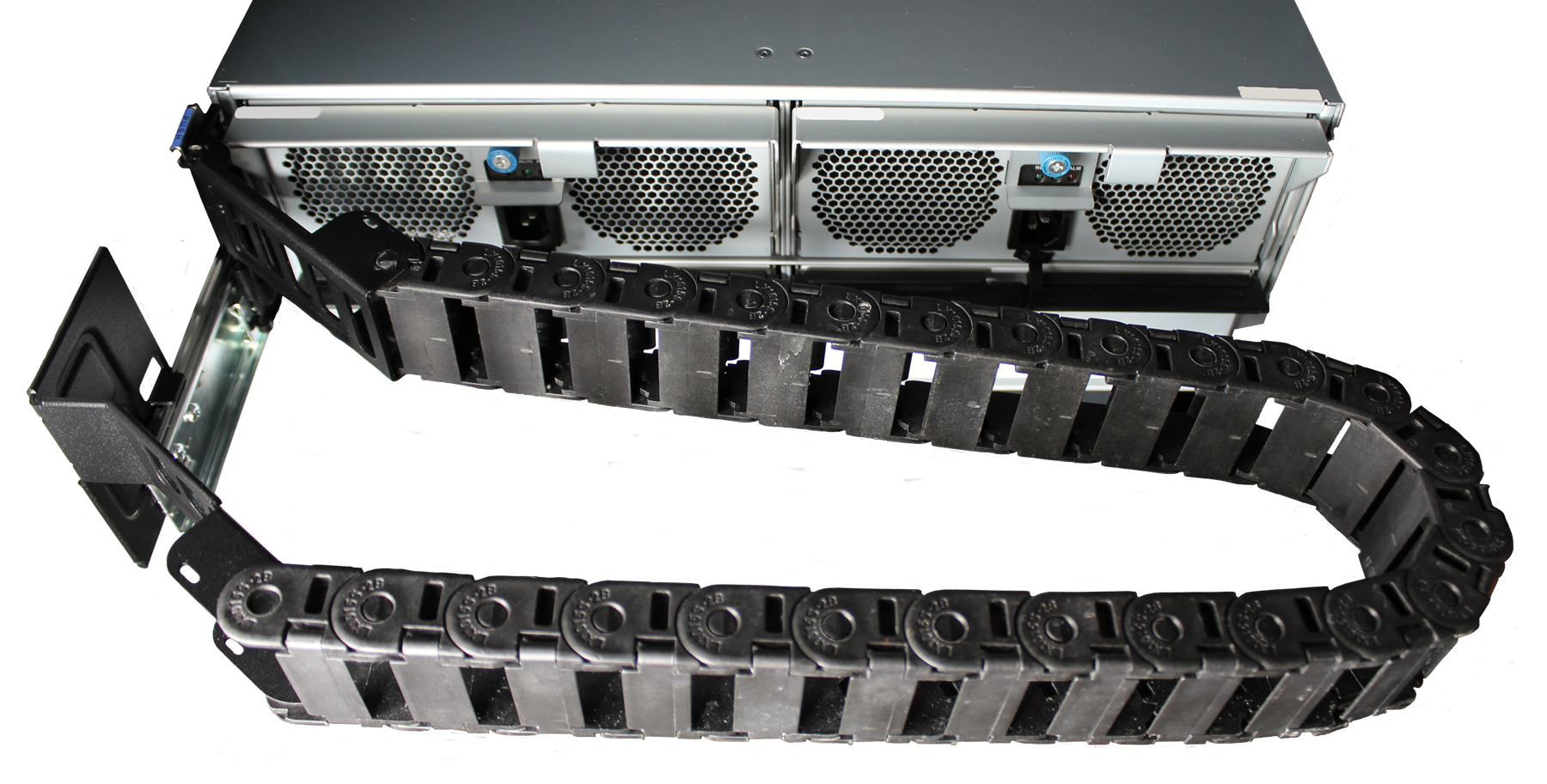
Completed Cable Management Arm assembly:
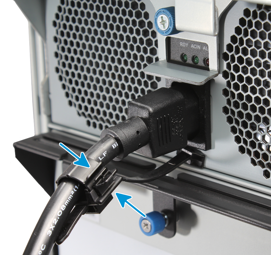
Power and data cables are routed through the flex housing. The tabs can be opened or removed to allow access or space for cable ends. Leave some slack in the cables at both ends to allow for movement of the arm and chassis.
16.6.6. Connect Power Cords
Do not plug the power cords into a power outlet yet. Connect a power cord to the back of one power supply, pressing it into the plastic clamp and pressing on the tab to lock it in place. Repeat the process for the second power supply and cord. Plug both power cords into a outlets. This turns on the ES60. Wait two minutes for the drives to start.
Service and management ports are not used during normal operation. Do not connect anything to them.
If the TrueNAS® system is already in operation, the expansion shelf can be powered on at any time.
16.6.7. Connect SAS Cables
The TrueNAS® system can remain on while the expansion shelf is connected.
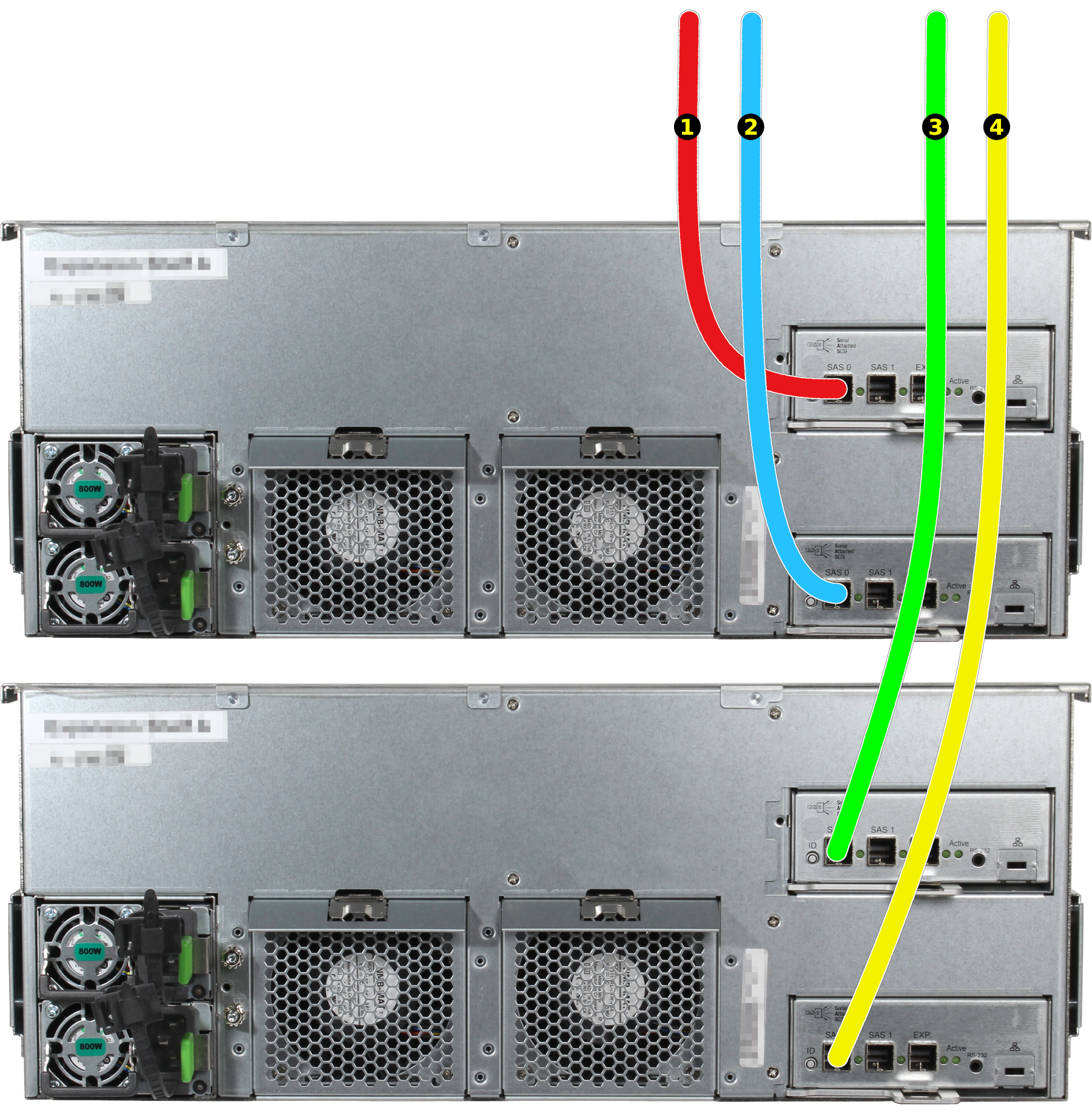
The ES60 is compatible with several TrueNAS® systems. Typical SAS cable connections for one or two ES60 expansion shelves to TrueNAS® High Availability (HA) systems are shown here. When a TrueNAS® unit with only a single storage controller is used, only cables #1 and #3 are connected.
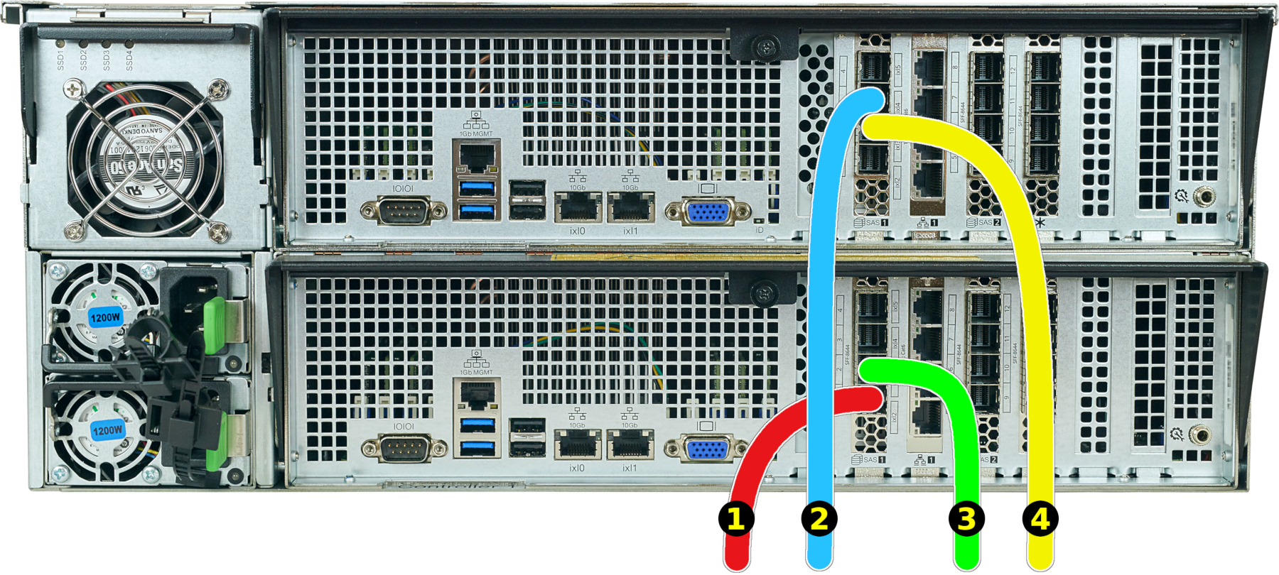
X-Series
The X20 supports a single ES60 expansion shelf. The ES60 must be connected to the first SAS ports (cables #1 and #2). An additional ES12 or ES24 expansion shelf can be connected to the second SAS ports with cables #3 and #4.
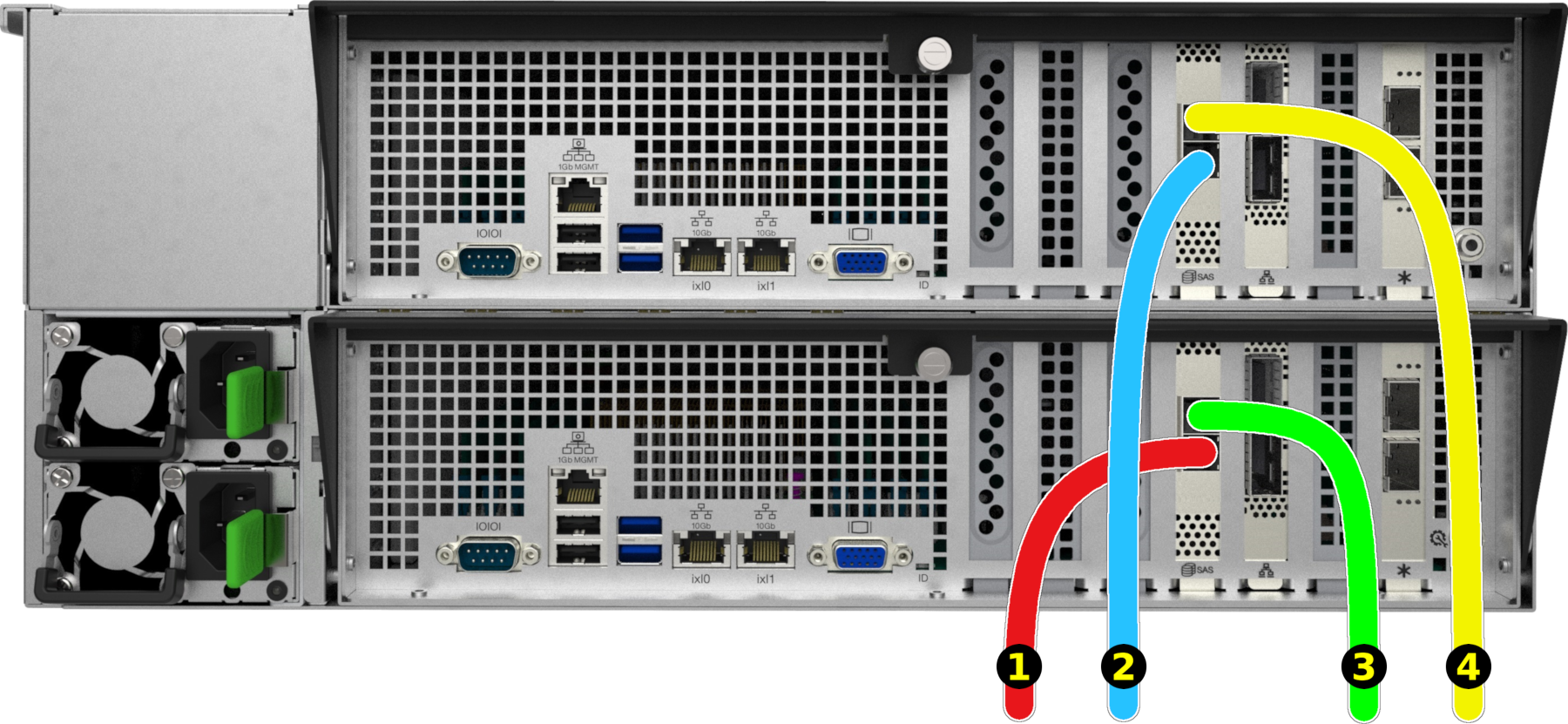
M-Series
The TrueNAS® M-Series support multiple ES60 expansion shelves, which can be combined with other TrueNAS® expansion shelves.
M40
M50
The SAS cables connect to the 1 ports on the ES60 expansion shelves.
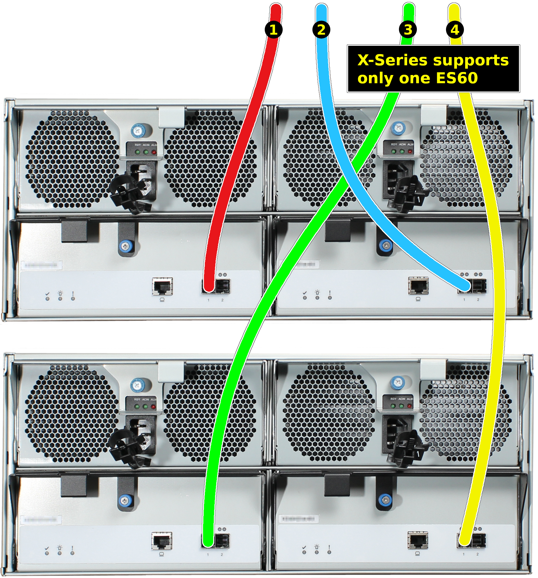
- Connect cable #1 to the first ES60, expansion controller 1 SAS 1 port.
- Connect cable #2 to the first ES60, expansion controller 2 SAS 1 port.
If a second ES60 is present:
- Connect cable #3 to the second ES60, expansion controller 1 SAS 1 port.
- Connect cable #4 to the second ES60, expansion controller 2 SAS 1 port.
16.6.8. Install Bezel (Optional)
The included bezel is not required for operation.
Line up the screw holes on the back of the bezel with the screw holes on the ears of the ES60. Install one upper screw from the back side of the left ES60 ear, then install a lower screw from the back of the right ES60 ear. Install the remaining two screws following the same diagonal pattern.
16.6.9. User Guide
The TrueNAS® User Guide with complete configuration instructions is available by clicking Guide in the TrueNAS® web interface or going directly to https://www.ixsystems.com/documentation/truenas/.