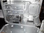
Building a PowerNAS G4 MDD

Status
Not open for further replies.

DaNilePharaoh

Explorer
Joined
Oct 17, 2014
Messages
79
g4 MDD-500x500.jpg


Greetings from Egypt, :)

I’ve been a mac user for more than 2 decades now, as an art director, photographer & marketing communications specialist, i’ve worked on several mac systems from Macintosh LC to the latest iMac and PowerMac. As a brand maker, during this period i developed a personal passion and loyalty for this brand!

Few years ago i started to building my own Hackintosh systems, thanx to tonymacx86 and the magnificent multibeast, unibeast, chimera developers and contributors.

Weeks ago i was looking for a storage solution for my Home workstation and BAAAM!
I discovered this forum and the FreeNAS thing, which was totally new for me... Did my homework and gave it a very good read, i’m talking hundreds of posts and videos. :) and now i’m thinking of building my FreeNAS system thanx to all of you, developers and contributors... and i want to share it with you.

Days later, I had to visit (M. Hamed) an old friend and a coworker who leads a reputable color separation/Printing House in Cairo, on the way to his office I noticed a couple of PowerMac G4 MDD (Mirror Drive Door) and a PowerMac G3 (Blue & White) Zip Drive Model, stored in a small storage room.

We finished our business and then i shocked him with a statement and an unexpected question:
i’m taking those old macs with me, how much you need for them?

He said: You can have them for free, on 1 condition, tell me frankly why you need them?

I said: I’m turning them into fish-tanks....... :) then i took them home.

I will never forget how my wife looked at me when i brought them home, she knew that extra cleaning should be done soon as they were in a mess condition. hahahahahah
0.jpg IMG_20140915_010701.jpg

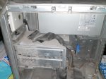
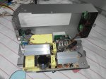
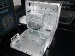
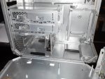
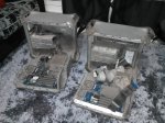
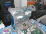
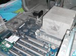
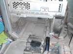
Covered with dust inside out, lots of missing parts like HD Cages, HD Drives, cables and one of the MDDs came with no power supply.

Tried to boot them up, hooked them to a monitor and power plug but there was nothing happening when you press the power button. ALL DEAD.
5.jpg 4.jpg 6.jpg

Technical Problems:
i wanted to:
1- keep the vintage, yet stylish look and feel of the cases.
2- Use as much as i can of the original parts.
3- Do only the necessary/minimum modifications to the cases.

Taking this in consideration i faced the following technical problems:
1- Due to the size of the dual optical drive housing and the below 2x drive cage its impossible to install a standard size motherboard in this case (it has to be removed).
2- The G4 MDD has a custom motherboard and case design (Top PCI Slots and bottom I/O ports).
3- The G4 MDD has a custom size Samsung 360w power supply approx. 5.25-6 x 12.7 x29cm, a standard ATX PSU will never fit in its location, SFX / Micro, Flex ATX / Mini ITX PSU might not fit also.

But i started the teardown process anyways, Knowing that i’ll find a solution later.


PowerShower G4:
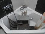
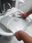
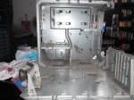
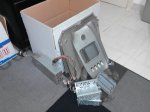
The tear-down process went very smooth as i was already an expert with this MDD and i worked on one for several years, but there was few tricky parts like removing the apple logo on the side panels, airport antenna and the back panel. but i found zillions of videos and articles describing how to disassemble them online.
9.jpg 10.jpg 12.jpg

Call it the PowerShower G4 or iShower G4 or whatever you wanna call it, it seemed the only way to clean more than 12 years of dust.

TO BE CONTINUED....
 

Attachments

  • 4.jpg
    4.jpg
    479.1 KB · Views: 585
Last edited:
DaNilePharaoh

Explorer
Joined
Oct 17, 2014
Messages
79
13.jpg 15.jpg

Hardware Salvage:
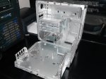
I got excited after the PowerShower, the case looks bright and shiny, and now i’m thinking, How the #@$* am I going to install an ATX system inside this case.

17.jpg 18.jpg

PSU
As i mentioned before, its almost impossible to install or to find (Locally) a PSU replacing the original, and at the same time fiting the original location.

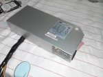
So i decided to give it a try with the original PSU, I made a paper clip test, connecting the Green (Power On - Pin 11) with the Black (Ground - Pin 12) and i hocked up a power cable.... Then I was like, ITS ALIVE... ALIVE...

luckily the 2x 60mm fans at the front of the PSU started to spin, blowing a massive amount of dust right to my face :) and it was as loud as a kitchen blender... FYI the MDDs was the loudest Powermac ever and often called "Wind Tunnel" by users referring to its noise.

20.jpg 21.jpg 23.jpg

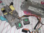
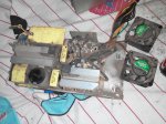
I started tearing down the PSU, found few living creatures inside, killed them all... removed the 2 fans and cleaned everything using a tooth brush, air blower, clean cloth and some quick dry electronics cleaner. Used a drop of machine oil on each fan, re-assembled everything, did the paper clip test again...

VOILA :) Quiet as a G4 MDD power supply.

24.jpg 25.jpg

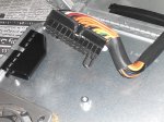
Now i simply have to change the pins as standard ATX to be able to re-use it with my system.

TO BE CONTINUED....
 
Last edited:
DaNilePharaoh

Explorer
Joined
Oct 17, 2014
Messages
79
Removing the Optical Drive Housing/Lower Drive Cage and cooling fan mount
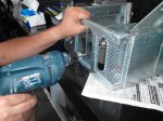
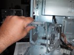
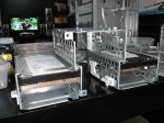
Was a must to install any Micro ATX, Mini ITX standard motherboard, and i simply done it by drilling out the rivets holding it to the case 3 at the fron, 2 at the bottom, 5 at the side of the case.

26.jpg 27.jpg

Re-Inventing the MDD Drive Cages
Now we are getting creative :) The MDD was designed to host 2x 5.25” Optical Drives + up to 4x 3.5” HDD, in 2 drive cages, one located under the power supply (vertically) and the other under the optical Drive Housing i just removed (horizontally) ...

17.jpg 18.jpg

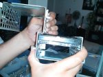
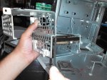
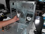
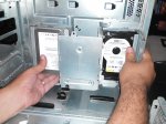
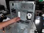
I wanted a solution to install at least 6 drives inside this case... then a brilliant idea popped into my mind, I took a third drive cage from the other MDD, then i combined the 3 cages together (a TOOLESS combination) using the tension of the installed HDDs as shown below.

28.jpg 29.jpg 31.jpg 32.jpg

This combination now can accommodate up to 8 Drives 6x 3.5” HDD and 2x 2.5” HDD/SSD in between the lower 2 cages, also it will provide the case with a decent cable management system as most of the PSU cables will run behind the middle drive cage. The drive cage locking mechanism is also functional for the right drive cage and the whole combination.

To mount this combination i only need to drill one hole (for the left cage) in the side of the case as the right drive cage already has its mount. Now i can install 8 drives and any size motherboard and aftermarket CPU cooler if i want too. You can rest in peace now Mr. Steve Jobs.

33.jpg 34.jpg


Hardware:
Here comes the toughest part of any build, Hardware choices...

i want:
1- A cheap Build so i decided to go with the good old man Mr. @joeschmuck AMD build with a little twist
(Server grade hardware is sky-high so its not an option for me).
2- ECC RAM support to protect myself from the forum guard dog Mr. @cyberjock and my valuable data.
3- At least 8TB of disk space.
4- Use as much as I can from the original components.
5- Hardware components available on the Egyptian market to avoid shipping costs.

So I made the following Purchase List:

MB: Asus M5A78L-M LX V2 = $50 (Local Price) - Purchased “was the last piece, no time to hesitate”
The @joeschmuck USB3 version would be a better alternative but i couldn’t find it in Egypt

CPU: AMD FX 4300 Quad Core 3.8GHz Black Edition = $87 (Local Price) Powerfull.
or
AMD Athlon II X2 280 AM3 Dual Core 3.6GHz 65W = $50 (Local Price) which sounds like a bargain.
or
AMD Sempron 145 Processor = $26 (Local Price) Dirt Cheap!.

RAM: Crucial (8GBx2) DDR3 1333 CL9 ECC UDIMM 1.35V/1.5V CT2CP102472BD1339 = $205
(Will have to order this from Amazon, Not available Locally)

HDD: 5x 2TB WD Red in RaidZ1 = 5 x $106 = $530 (Local Price)
or
5x 2TB WD Green in RaidZ1 = 5 x $80 = $400 (Local Price)

NIC: Intel PWLA8391GT PRO/1000 GT PCI Network Adapter = $26 (Local Price)


Now the questions are...

1- Do you think the Athlon II will be a good choice for this system? will it support ECC?
2- its kinda too late to ask, Can this MB support 3TB HD? for future upgrades
3- Online PSU Calculator results was 220w (Minimum) 270w (Recommended PSU Wattage) so the original Samsung 360w PSU should be fine running this system... what happens if the PSU failed for some reason?

Your thoughts are more than welcome....

TO BE CONTINUED....
 
Last edited:
cyberjock

Inactive Account
Joined
Mar 25, 2012
Messages
19,526
1. No clue if a given AMD CPU will "support ECC" but be aware of the fact that it's impossible to actually validate that ECC works on *any* AMD CPU. So "buyer beware".
2. No clue.
3. 360w should be fine. If the PSU fails then the PSU fails. Life goes on.
 

DaNilePharaoh

Explorer
Joined
Oct 17, 2014
Messages
79
You only have to whisper "non-server grade" for the Rottweiler to come n bite ya :)
your quick answer is highly appreciated,

I believe the AMD was the right choice for me, let me explain why
Taking in consideration that Supermicro products does not exist in Egypt and the shipping cost+customs from amazon to Egypt is HUGE.
I had 2 choices:

1- To go Intel and
- Buy a much more expensive H87, z87 or higher to be sure it supports ECC, which cost locally as much as a good supermicro board on amazon.
- Most H87, z87 and above found here are ATX form factor (24.4x30.5cm) that won't fit inside the G4 case.
- So i'll have to buy a new case and power supply (more cost) and sacrifice all the fun i'm having now modding the MDD.
or
2- To go AMD and
- Reduce the expenses, invest more on extra ECC Ram or storage.
- Find a decent 6x SATA, ECC and uATX or Mini ITX form factor motherboard.
- Give the whole freeNAS project a test drive for cheap.
- Enjoy the MDD case modding process.
- Break the FreeNAS rules and system requirements, trying to prove that its possible (which is double the fun) :)
- Build a cheap reliable system that can be turned into a HTPC or Gaming rig for my little 9 years old son. (in case i did not like the experience or it failed to operate FreeNAS ZFS properly)

For the PSU question I meant, can a sudden PSU failure cause a data corruption or make my pool unreadable or mountable somehow? thanx
 

cyberjock

Inactive Account
Joined
Mar 25, 2012
Messages
19,526
- Buy a much more expensive H87, z87 or higher to be sure it supports ECC, which cost locally as much as a good supermicro board on amazon.

No, that wouldn't have worked. Those chipsets are desktop and do not support ECC. :p
- Most H87, z87 and above found here are ATX form factor (24.4x30.5cm) that won't fit inside the G4 ca

2- To go AMD and
- Reduce the expenses, invest more on extra ECC Ram or storage.
- Find a decent 6x SATA, ECC and uATX or Mini ITX form factor motherboard.
- Give the whole freeNAS project a test drive for cheap.
- Enjoy the MDD case modding process.
- Break the FreeNAS rules and system requirements, trying to prove that its possible (which is double the fun) :)
- Build a cheap reliable system that can be turned into a HTPC or Gaming rig for my little 9 years old son. (in case i did not like the experience or it failed to operate FreeNAS ZFS properly)

Do not be fooled. We've had lots of people do what we tell them not to do under the guise of "proving it's possible". We don't say it's impossible. We do often tell people it's a bad idea. And quite a few of those users argue with us, but months later have no data. There's a difference between what is possible and what is a good idea. I could easily argue that it's not "a good idea", but I won't disagree with you and argue that it's not possible.

For the PSU question I meant, can a sudden PSU failure cause a data corruption or make my pool unreadable or mountable somehow? thanx

Yes, it's possible depending on your PSU. All you need is a PSU to overvolt everything in your computer for a few seconds and you'll never seen any of the components work again. Problems like this are precisely why backups are still very important. ;)

Don't get me wrong, this is a fun project and I'm curious to see how it all works out. But I will always put form over function. I'd rather have a trustworthy stable system that looks butt-ugly than a pretty system that might eat my data at any moment. ;)
 

Ericloewe

Server Wrangler
Moderator
Joined
Feb 15, 2014
Messages
20,194
Don't get me wrong, this is a fun project and I'm curious to see how it all works out. But I will always put form over function. I'd rather have a trustworthy stable system that looks butt-ugly than a pretty system that might eat my data at any moment. ;)

Don't you mean function over form? Unless of course you have the pictures of those who argued against ECC and later came back with pools destroyed by RAM problems carefully painted onto the grilles of the drive trays on your Supermicro chassis (If you do, you must not tell the cops you're a forum admin keeping track of victims of their own beliefs - they'll probably react badly. Tell them it's an art installation.):D

@DaNilePharaoh - All I can say is holy crap. The endeavor of turning those things into usable modern servers pales in comparison to the unbelievable job you did cleaning everything. That PSU looks brand new.

One unfortunate thing about the PSU, though: It's quite biased towards the minor rails, so it may have trouble with modern loads if you try to run it close to its maximum rating - I suggest you avoid loading it too much.
 

cyberjock

Inactive Account
Joined
Mar 25, 2012
Messages
19,526
OOps. I meant function over form. That's what I get for not sleeping well. :P
 

joeschmuck

Old Man
Moderator
Joined
May 28, 2011
Messages
10,994
Not sure why the @joeschmuck didn't flag me to read your posting but I found it.

As for the AMD CPU's you had selected, as far as I can tell only the FX-4300 will support ECC RAM. If you do go down the AMD path then I would highly recommend the FX x3xx series (example 4300, 4320, 8300) of CPUs (Vishera core) as I know they support ECC memory. Do not use the Piledriver core, those do not support ECC. To Cyberjocks point, the only way you can tell ECC is being supported is in the BIOS, and MemTest does tell you that you have ECC RAM installed. What you will not get while running FreeNAS is something telling you that your ECC RAM is in good health. I would expect my MB to start beeping or something if it ever encounters an ECC problem it couldn't fix. I have to take it on faith because ASUS is not very forthcoming with details about how they implemented the ECC.

Also I do recommend adding an Intel NIC card as the RealTek can have issues with large file transfers. When I was running versions of FreeNAS before 9.2.x I never saw a problem however now I do so I had to break down and add the NIC.

The USB3 version of that MB is fine if you were going to use USB3 but to date I have not used it. I would only have used it for the boot flash drive anyway and it's no big deal if it takes me 1 minute to boot or 2 minutes to boot. I don't reboot that often, now it's more likely that I reboot whenever I perform a software upgrade or a severe electrical storm is coming my way.

Lets talk about your power supply... Please post the specs of the outputs. The photo was a bit hard to make out but I think it said 5V@20A, 12V@16.6A, 3.3V@17A. This information will tell me if your PS can handle a modern CPU, but if I got the specs correct, you should be fine from this aspect. Also note that most MBs now have a 4 Pin 12V power connector for the CPU and the Asus MB has it. You will need to wire that in as well. Without it and you run into stability issues. Also, since it's an old looking PS, check the electrolytic capacitors and ensure they are all good as these are what typically fail in a power supply. On the 24 pin connector from your power supply it looks like you have a +25VDC output which you cannot use, but more importantly you do not have a Power Good line coming out of the power supply. Curious how you will be getting around that? Guess you could take a capacitor between the +5VDC line and the PG pin and force a small delay while the PS is coming up. I wouldn't wire it directly to the +5V line but that is your call and an option.

As for obtaining the same storage amount you have spec'd above in your parts list, your ~8TB (7.3TB) of storage, I would recommend using 4TB hard drives for a few reasons...
1) Power Draw of powering on your system will cause a spike. Your PS might be able to handle it but you need to factor that in. Using fewer hard drives does have that benefit.
2) Cooler internal temps with less hard drives.

So I'd recommend four 4TB drives, you can choose the WD Green series if you like, they have been reported to work fine. I personally would pay a few extra bucks to get the warranty of the Reds. There are other drives to choose from but it's really going to be up to you. And I say 4 drives because I'd recommend going with RAIDZ2 vice RAIDZ1. However it depends on what you want, all we can do is promote our experiences.

One thing I'm sure you are aware of but I'd like to point out anyway, ensure that you have good airflow over the hard drives and your MB.

You have a nice project going on here, I will definitely follow it.
 

DaNilePharaoh

Explorer
Joined
Oct 17, 2014
Messages
79
No, that wouldn't have worked. Those chipsets are desktop and do not support ECC. :p
- Most H87, z87 and above found here are ATX form factor (24.4x30.5cm) that won't fit inside the G4 ca

I meant a high-end desktop MB, it was not my intention to use one from the beginning :) so i did not bother remembering the chipset name

We do often tell people it's a bad idea.

This is exactly what my wife said when i came home with the 3 macs :) and usually when she say so, i'm sure that im doing the right thing :p hahahahahah

Yes, it's possible depending on your PSU. All you need is a PSU to overvolt everything in your computer for a few seconds and you'll never seen any of the components work again. Problems like this are precisely why backups are still very important. ;)

This could happen to a brand new corsair 80+ gold, so i guess i don't have to worry, lets hope for the best

Don't get me wrong, this is a fun project and I'm curious to see how it all works out. But I will always put form over function. I'd rather have a trustworthy stable system that looks butt-ugly than a pretty system that might eat my data at any moment. ;)

i like the name you created, i still have 2 extra macs :) im thinking seriously now of a powerBUTT G3 :p
sorry for the delay reply :) when you said "form over function" i knew its time for us all to sleep
 

DaNilePharaoh

Explorer
Joined
Oct 17, 2014
Messages
79
- All I can say is holy crap. The endeavor of turning those things into usable modern servers pales in comparison to the unbelievable job you did cleaning everything. That PSU looks brand new.

One unfortunate thing about the PSU, though: It's quite biased towards the minor rails, so it may have trouble with modern loads if you try to run it close to its maximum rating - I suggest you avoid loading it too much.

Agree with you 100% overloading a more than 10 years old PSU doesn't sound like a good idea. that's why i was asking about over 2tb support for this MB, to reduce the load as Mr. @joeschmuck advised also.

This PSU was design to run 2 optical drives + 4 HDD, so i believe I'm safe anywhere below or = 6 HDDs... lower is better to reduce load, heat and power consumption.
 

DaNilePharaoh

Explorer
Joined
Oct 17, 2014
Messages
79
Do not use the Piledriver core,

I'm a bit confused now! isn't the FX 4300 a piledriver cpu?
http://en.wikipedia.org/wiki/Piledriver_(microarchitecture)

Also I do recommend adding an Intel NIC card as the RealTek can have issues with large file transfers. When I was running versions of FreeNAS before 9.2.x I never saw a problem however now I do so I had to break down and add the NIC.

what do you think of my NIC choice? do you think i should go PCIe instead of PCI? i guess it wont make a big of a difference

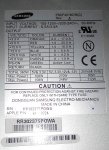
Lets talk about your power supply... Please post the specs of the outputs. The photo was a bit hard to make out but I think it said 5V@20A, 12V@16.6A, 3.3V@17A. This information will tell me if your PS can handle a modern CPU, but if I got the specs correct, you should be fine from this aspect. Also note that most MBs now have a 4 Pin 12V power connector for the CPU and the Asus MB has it. You will need to wire that in as well. Without it and you run into stability issues. Also, since it's an old looking PS, check the electrolytic capacitors and ensure they are all good as these are what typically fail in a power supply.

Please find the below PSU label photo, i guess it should work fine as you mentioned.
IMG_20141019_005316.jpg

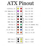
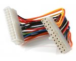
The PSU have only 6x 4 pin molex + the 24 pin ATX Cable that is pinned out differently than the normal ATX PSU

ATX.jpg MDD.jpg

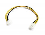
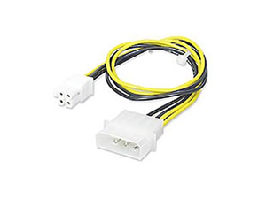
so i'll have to re-pin it, then buy a P4 4-pin 12V Power Connector to Molex Cable Adapter for the MB 12v socket
61+B5-N8XVL._SL1500_.jpg IMG_20141019_010059.jpg

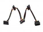
also i'll need a couple of these for the sata hdds (4-Pin Molex Male to 4 15-Pin SATA II Female Power Cable)
41EZEzHcMCL.jpg

The capacitors looks fine, Japanese made which is a plus :)

On the 24 pin connector from your power supply it looks like you have a +25VDC output which you cannot use, but more importantly you do not have a Power Good line coming out of the power supply. Curious how you will be getting around that? Guess you could take a capacitor between the +5VDC line and the PG pin and force a small delay while the PS is coming up. I wouldn't wire it directly to the +5V line but that is your call and an option.

English please :)
i knew those white and gray wires will make me suffer somehow :)

So I'd recommend four 4TB drives, you can choose the WD Green series if you like, they have been reported to work fine. I personally would pay a few extra bucks to get the warranty of the Reds. There are other drives to choose from but it's really going to be up to you. And I say 4 drives because I'd recommend going with RAIDZ2 vice RAIDZ1. However it depends on what you want, all we can do is promote our experiences.

Will have to check the local prices for the 3 or above tb hdd as they are considered new tech here and the prices are still high.

One thing I'm sure you are aware of but I'd like to point out anyway, ensure that you have good airflow over the hard drives and your MB.

You have a nice project going on here, I will definitely follow it.

i'm solving one problem at a time :) ventilation is always a concern, specially in the HOT EGYPTIAN summer, temperature go as high as 55º here...

Thanx for the complement and support :)
 
Last edited:

joeschmuck

Old Man
Moderator
Joined
May 28, 2011
Messages
10,994
I'm a bit confused now! isn't the FX 4300 a piledriver cpu?
http://en.wikipedia.org/wiki/Piledriver_(microarchitecture)
I misread something, you are correct. Here is the link I used, it actually tells you that ECC is supported. http://en.wikipedia.org/wiki/List_of_AMD_FX_microprocessors

what do you think of my NIC choice? do you think i should go PCIe instead of PCI? i guess it wont make a big of a difference
Choose the card that you know is compatible with your MB. Since the Asus MB has three PCIe and one PCI connection, I'd buy the PCIe as it is also more compatible with other MB's in the future but to be honest, it shouldn't matter at all functionally.

The power supply specs look nice so if you can re-pin the 24 pin connector properly and make the Power Good signal, you should be good to drive six hard drives if you want and the computer, however due to the age of the power supply, I still feel the four drive option would do you well.

One more thing about the 24 pin connector... Is it the proper ATX type connector because the pins have unique shapes to ensure they cannot be plugged into the wrong connector. You should test fit it into an ATX computer plug. You will still need to add a 4 pin connector for the CPU extra power, see attached image for an easy connection example.
A00Z_1_20130126107964966.jpg
 
Last edited:

DaNilePharaoh

Explorer
Joined
Oct 17, 2014
Messages
79
I misread something, you are correct. Here is the link I used, it actually tells you that ECC is supported. http://en.wikipedia.org/wiki/List_of_AMD_FX_microprocessors
http://en.wikipedia.org/wiki/List_of_AMD_FX_microprocessors

CPU nicknames can be confusing :) never mind
I can get FX-4300 or 4350 locally, but i'm more for your choice of the FX-4300 (95W).
The 4350 is more power hungry (125W)


but more importantly you do not have a Power Good line coming out of the power supply. Curious how you will be getting around that? Guess you could take a capacitor between the +5VDC line and the PG pin and force a small delay while the PS is coming up. I wouldn't wire it directly to the +5V line but that is your call and an option.
I'll ignore both pin 14 +25v coming out of the PSU and pin 18 -5v going to the MB
For the POK pin solution, can you please explain more (the capacitor thing), why do you think a direct connection to a +5v line is not a good idea?

One more thing about the 24 pin connector... Is it the proper ATX type connector because the pins have unique shapes to ensure they cannot be plugged into the wrong connector. You should test fit it into an ATX computer plug. You will still need to add a 4 pin connector for the CPU extra power, see attached image for an easy connection example.
A00Z_1_20130126107964966.jpg

I'll get a 24 Pin ATX Power Extension Cable, cut the female side of it
41Cy0VoNcLL.jpg
also i'll have to cut the male PSU 24 Pin cable and re-wire (match colors, solder & isolate) each cable together.
 

joeschmuck

Old Man
Moderator
Joined
May 28, 2011
Messages
10,994
I'll ignore both pin 14 +25v coming out of the PSU and pin 18 -5v going to the MB
For the POK pin solution, can you please explain more (the capacitor thing), why do you think a direct connection to a +5v line is not a good idea?

Yes, the -5VDC line is no longer required.

The Power Good signal or POK is a 5VDC signal is generated by the power supply once the voltages have stabilized and it then allows the MB to start running. In a cheap power supply they will make a direct connection from +5VDC to the POK line but in most power supplies there is a circuit to actually verify the power levels are okay. Lets say your power supply had a significant dip in +12VDC when you power on because of the hard drives spinning up. That dip could cause the CPU to hang. Normally with POK it would cause the CPU to reset. So when some folks say their computer reboots without warning, it could very well be the power supply causing it.

So if it were me using your power supply, I would wire in a time delay by some method and for that delay to be about .5 seconds, or longer if you want. The goal is to ensure the power is stable. The RC circuit is just a resistor and capacitor and the simplest way to create a time delay, just not very accurate for true timing. So you would take a capacitor and a resistor of certain values and wire it up. You would take a resistor and wire it between +5VDC and the POK line, also you would take a capacitor and wire it between the POK line and GND. When you turn on the power the capacitor will be fully discharged and start charging through the resistor. After a period of time the capacitor will have charged to the threshold point for the MB to qualify the POK line.

Check out this site http://en.wikipedia.org/wiki/RC_circuit
Scroll down to the Series section and the diagram is what I'm talking about. The Vin would be the +5VDC on top and GND on bottom. The Vc would be the POK line on top. And scroll down to Time Domain Considerations because that is what we would use this circuit for. If you go to crank in the calculations, I'd shoot for +2.5VDC as your goal to reach in .5 seconds, not the full +5VDC because I do not know what the voltage threshold is to qualify POK.

You can also look into Power On Reset (POR) circuits, that is what this is. You just want something with a delay longer than a few milliseconds.

Here is a link to something I posted a long time ago where I needed a way to turn on the power to a small NAS when power was restored to it. I used the capacitor to short out the power switch. It's the same principle but a slightly different circuit design. http://forums.dlink.com/index.php?topic=9038.0

I hope this wasn't too confusing for you. If you put a little time into the formulas you should be able to come up with some values, and I haven't played with those formulas in many decades. When using electrolytic capacitors, ensure you wire up the polarity correctly.
 

DaNilePharaoh

Explorer
Joined
Oct 17, 2014
Messages
79
So if it were me using your power supply, I would wire in a time delay by some method and for that delay to be about .5 seconds, or longer if you want. The goal is to ensure the power is stable. The RC circuit is just a resistor and capacitor and the simplest way to create a time delay, just not very accurate for true timing. So you would take a capacitor and a resistor of certain values and wire it up. You would take a resistor and wire it between +5VDC and the POK line, also you would take a capacitor and wire it between the POK line and GND. When you turn on the power the capacitor will be fully discharged and start charging through the resistor. After a period of time the capacitor will have charged to the threshold point for the MB to qualify the POK line.

I guess i got the concept, maybe an easy solution too, what do you think of this?
View: http://www.amazon.com/SRD-5VDC-SL-C-Electronical-Delay-Relay-Module/dp/B00CWA4TZ8/ref=sr_1_fkmr0_2?ie=UTF8&qid=1413733391&sr=8-2-fkmr0&keywords=5v+Delay+Timer+Switch+Adjustable+Module


Check out this site http://en.wikipedia.org/wiki/RC_circuit
Scroll down to the Series section and the diagram is what I'm talking about. The Vin would be the +5VDC on top and GND on bottom. The Vc would be the POK line on top. And scroll down to Time Domain Considerations because that is what we would use this circuit for. If you go to crank in the calculations, I'd shoot for +2.5VDC as your goal to reach in .5 seconds, not the full +5VDC because I do not know what the voltage threshold is to qualify POK.

Im better reading hieroglyphic than this :)

Here is a link to something I posted a long time ago where I needed a way to turn on the power to a small NAS when power was restored to it. I used the capacitor to short out the power switch. It's the same principle but a slightly different circuit design. http://forums.dlink.com/index.php?topic=9038.0

super like

I hope this wasn't too confusing for you. If you put a little time into the formulas you should be able to come up with some values, and I haven't played with those formulas in many decades. When using electrolytic capacitors, ensure you wire up the polarity correctly.

It was :) i'm all new to electricity also i really need more time to study it all.
the question now is, how come apple/samsung didn't do this delay thing?! if its so important... they might have done it internally?? is it possible?
 

joeschmuck

Old Man
Moderator
Joined
May 28, 2011
Messages
10,994
The question now is, how come apple/samsung didn't do this delay thing?! if its so important... they might have done it internally?? is it possible?
Anything I say here would be pure speculation.

As for the timer module you listed, I didn't see any specs on the delay time and you really don't want a 10 second minimum delay.

To simplify things for you try this approach...
Hook up +5VDC to POK and see if the computer boots fine under load. Maybe all will be fine. Or you could just purchase a 2200 ohm 1/4watt (or 1/2 watt) resistor and a 470uF 10V (or higher voltage) capacitor.

To make the calculations easier I located this web site, just scroll down to boxes to fill in. In the fields enter R= 2200, Vb=5, C=470 and RC will display the time in seconds for the capacitor to become fully charged which is 1.034 seconds. Keep in mind that we still don't know what voltage level the POK signal the MB will say all is okay so use 2VDC as the level for argument and try to ensure that is about .3 seconds at least. Depending on the components that you can obtain, plug in different values but the 5V remains constant always. Parts should be very cheap. If you have to make changes in the parts, a larger capacitor is better than a higher resistor value.
 

mjws00

Guru
Joined
Jul 25, 2014
Messages
798
Cool project. Not sure if you've looked at sfx or tfx or even flex power supplies... but they make awesome small gear that will likely fit with no additional mods, in addition to running quiet and cool. I might hack it up as well. But it would be a coin flip if I spotted something that would fit on the shelf and wasn't just playing.

Fun to watch @joeschmuck in his native habitat.
 

Ericloewe

Server Wrangler
Moderator
Joined
Feb 15, 2014
Messages
20,194
Yeah. Some 'deep magic' going on here. If I were to try it, I'd probably mess up the incantation and teleport to chthulu's lair (and cook my FreeNAS to boot).

Don't worry, giant squids are very good electrical engineers. Cthulhu will gladly help you along and teach you the basics of Capacitors and Inductors.

The only deep magic here is hidden inside that PSU.
 
Status
Not open for further replies.
Top