4. System
The System section of the web interface contains these entries:
- Information provides general TrueNAS® system information such as hostname, operating system version, platform, and uptime
- General configures general settings such as HTTPS access, the language, and the timezone
- Boot creates, renames, and deletes boot environments. It also shows the condition of the Boot Volume
- Advanced configures advanced settings such as the serial console, swap space, and console messages
- Email configures the email address to receive notifications
- System Dataset configures the location where logs and reporting graphs are stored
- Tunables provides a front-end for tuning in real-time and to load additional kernel modules at boot time
- Cloud Credentials is used to enter connection credentials for remote cloud service providers
- Update performs upgrades and checks for system updates
- Alerts lists the available Alert conditions and provides configuration of the notification frequency for each alert
- Alert Services configures services used to notify the administrator about system events
- CAs: import or create internal or intermediate CAs (Certificate Authorities)
- Certificates: import existing certificates or create self-signed certificates
- Support: view licensing information or create a support ticket
- Proactive Support: enable and configure automatic proactive support (Silver or Gold support coverage only)
- View Enclosure: view status of disk enclosures
- Failover: manage High Availability
Each of these is described in more detail in this section.
4.1. Information
displays general information about the TrueNAS® system. An example is seen in Figure 4.1.1.
The information includes hostname, build version, type of CPU (platform), amount of memory, current system time, system uptime, number of users connected at the console or by serial, telnet, or SSH connections, and current load average. On systems supplied or certified by iXsystems, an additional Serial Number field showing the hardware serial number is displayed.
To change the system hostname, click the Edit button, type in the new hostname, and click OK. The hostname must include the domain name. If the network does not use a domain name, add .local after the hostname.
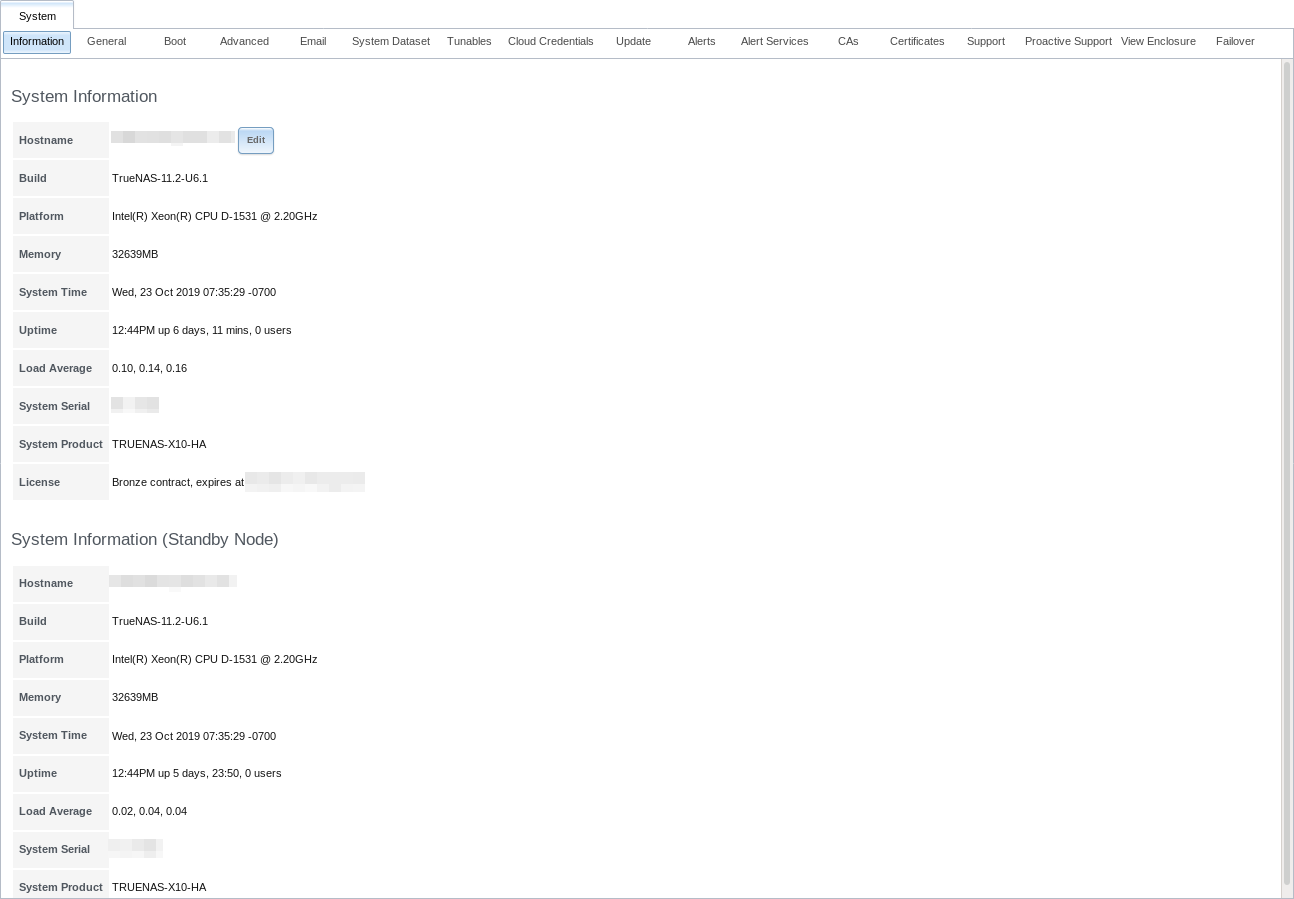
Fig. 4.1.1 System Information Tab
4.2. General
is shown in Figure 4.2.1.
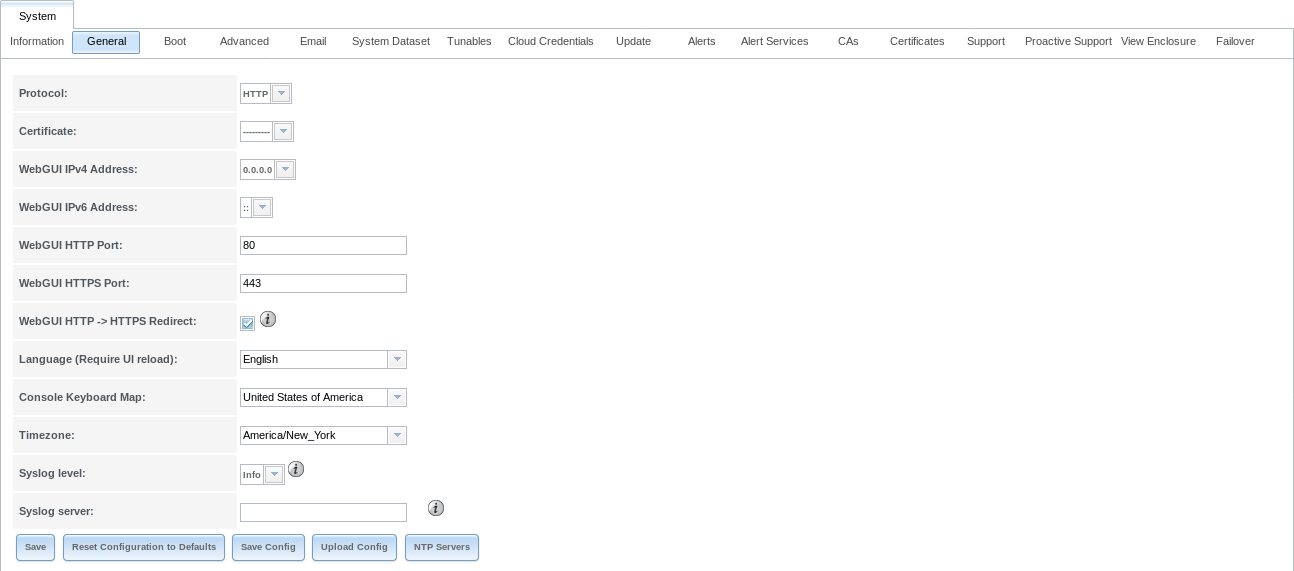
Fig. 4.2.1 General Screen
Table 4.2.1 summarizes the configurable settings in the General tab:
| Setting | Value | Description |
|---|---|---|
| Protocol | drop-down menu | Set the web protocol to use when connecting to the web interface from a browser. To change the default HTTP to HTTPS or to HTTP+HTTPS, select a certificate to use in Certificate. If there are no certificates, first create a CA then a certificate. |
| Certificate | drop-down menu | Required for HTTPS. Select a certificate to use for encrypted connections. |
| WebGUI IPv4 Address | drop-down menu | Choose a recent IP address to limit the usage when accessing the web interface. The built-in HTTP server binds to the wildcard address of 0.0.0.0 (any address) and issues an alert if the specified address becomes unavailable. |
| WebGUI IPv6 Address | drop-down menu | Choose a recent IPv6 address to limit the usage when accessing the web interface. The built-in HTTP server binds to any address issues an alert if the specified address becomes unavailable. |
| WebGUI HTTP Port | integer | Allow configuring a non-standard port for accessing the web interface over HTTP. Changing this setting can also require changing a Firefox configuration setting. |
| WebGUI HTTPS Port | integer | Allow configuring a non-standard port for accessing the web interface over HTTPS. |
| WebGUI HTTP –> HTTPS Redirect | checkbox | Set to redirect HTTP connections to HTTPS. HTTPS must be selected in Protocol. |
| Language | drop-down menu | Select a localization. |
| Console Keyboard Map | drop-down menu | Select a keyboard layout. |
| Timezone | drop-down menu | Select a timezone. |
| Syslog level | drop-down menu | When Syslog server is defined, only logs matching this level are sent. |
| Syslog server | string | Enter an IP address_or_hostname:optional_port_number to send logs to. Configure to write log entries to both the console and the remote server. |
After making any changes, click the Save button.
This screen also contains these buttons:
Reset Configuration to Defaults: reset the configuration database to the default base version. This does not delete user SSH keys or any other data stored in a user home directory. Since configuration changes stored in the configuration database are erased, this option is useful when a mistake has been made or to return a test system to the original configuration.
Save Config: save a backup copy of the current configuration database in the format hostname-version-architecture to the computer accessing the administrative interface. Saving the configuration after making any configuration changes is highly recommended. TrueNAS® automatically backs up the configuration database to the system dataset every morning at 3:45. However, this backup does not occur if the system is shut down at that time. If the system dataset is stored on the boot pool and the boot pool becomes unavailable, the backup will also not be available. The location of the system dataset is viewed or set using .
Note
SSH keys are not stored in the configuration database
and must be backed up separately. System host keys are files with
names beginning with ssh_host_ in /usr/local/etc/ssh/.
The root user keys are stored in /root/.ssh.
There are two types of passwords. User account passwords for the base operating system are stored as hashed values, do not need to be encrypted to be secure, and are saved in the system configuration backup. Other passwords, like iSCSI CHAP passwords, Active Directory bind credentials, and cloud credentials are stored in an encrypted form to prevent them from being visible as plain text in the saved system configuration. The key or seed for this encryption is normally stored only on the operating system device. When Save Config is chosen, a dialog gives the option to Export Password Secret Seed with the saved configuration, allowing the configuration file to be restored to a different operating system device where the decryption seed is not already present. Configuration backups containing the seed must be physically secured to prevent decryption of passwords and unauthorized access.
Warning
The Export Password Secret Seed option is off by default and should only be used when making a configuration backup that will be stored securely. After moving a configuration to new hardware, media containing a configuration backup with a decryption seed should be securely erased before reuse.
Upload Config: allows browsing to the location of a previously saved configuration file to restore that configuration. The screen turns red as an indication that the system will need to reboot to load the restored configuration.
NTP Servers: The network time protocol (NTP) is used to synchronize the time on the computers in a network. Accurate time is necessary for the successful operation of time sensitive applications such as Active Directory or other directory services. By default, TrueNAS® is pre-configured to use three public NTP servers. If the network is using a directory service, ensure that the TrueNAS® system and the server running the directory service have been configured to use the same NTP servers.
Available NTP servers can be found at https://support.ntp.org/bin/view/Servers/NTPPoolServers. For time accuracy, choose NTP servers that are geographically close to the physical location of the TrueNAS® system.
Click to add an NTP server. Figure 4.2.2 shows the screen that appears. Table 4.2.2 summarizes the options available when adding an NTP server. ntp.conf(5) explains these options in more detail.
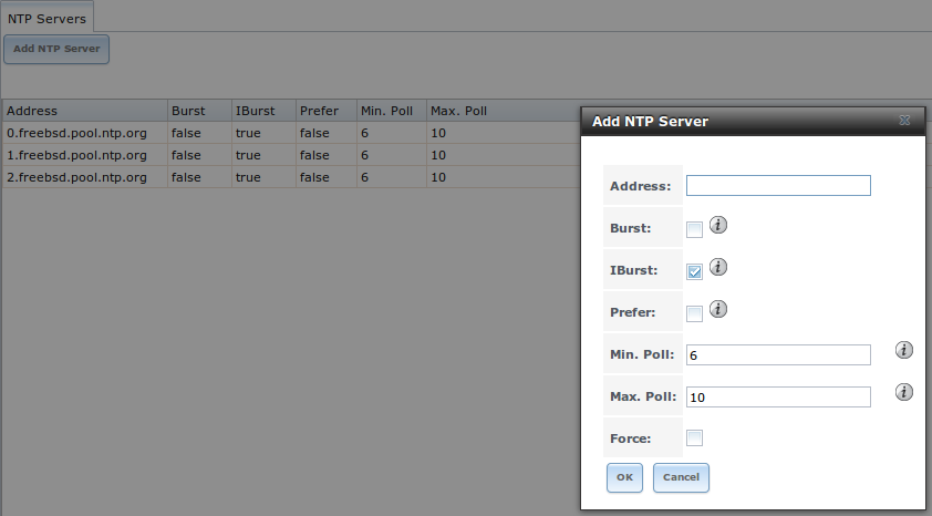
Fig. 4.2.2 Add an NTP Server
| Setting | Value | Description |
|---|---|---|
| Address | string | Enter the hostname or IP address of the NTP server. |
| Burst | checkbox | Recommended when Max. Poll is greater than 10. Only use on private servers. Do not use with a public NTP server. |
| IBurst | checkbox | Speed up the initial synchronization, taking seconds rather than minutes. |
| Prefer | checkbox | This option is only recommended for highly accurate NTP servers, such as those with time monitoring hardware. |
| Min. Poll | integer | Minimum polling time in seconds. Must be a power of 2, and cannot be lower than 4 or higher than Max. Poll. |
| Max. Poll | integer | Maximum polling time in seconds. Must be a power of 2, and cannot be higher than 17 or lower than Min. Poll. |
| Force | checkbox | Force the addition of the NTP server, even if it is currently unreachable. |
4.3. Boot
TrueNAS® supports a ZFS feature known as multiple boot environments. With multiple boot environments, the process of updating the operating system becomes a low-risk operation. The updater automatically creates a snapshot of the current boot environment and adds it to the boot menu before applying the update.
Note
Boot environments are separate from the configuration database. Boot environments are a snapshot of the operating system at a specified time. When a TrueNAS® system boots, it loads the specified boot environment, or operating system, then reads the configuration database to load the current configuration values. If the intent is to make configuration changes rather than operating system changes, make a backup of the configuration database first using .
As seen in Figure 4.3.1, TrueNAS® displays the condition and statistics of the Boot Volume. It also shows the two boot environments that are created when TrueNAS® is installed. The system will boot into the default boot environment and users can make their changes and update from this version. The Initial-Install boot environment can be booted into if the system needs to be returned to a non-configured version of the installation.
If the Wizard was used, a third boot environment called
Wizard-date is also created, indicating the date and time
the Wizard was run.
Fig. 4.3.1 Viewing Boot Environments
Each boot environment entry contains this information:
- Name: the name of the boot entry as it will appear in the boot menu.
- Active: indicates which entry will boot by default if the user does not select another entry in the boot menu.
- Created: indicates the date and time the boot entry was created.
- Keep: indicates whether or not this boot environment can be pruned if an update does not have enough space to proceed. Click Keep for an entry if that boot environment should not be automatically pruned.
Highlight an entry to view the configuration buttons for it. These configuration buttons are shown:
- Clone: makes a new boot environment from the selected boot environment.
- Delete: used to delete the highlighted entry, which also removes that entry from the boot menu. Since an activated entry cannot be deleted, this button does not appear for the active boot environment. To delete an entry that is currently activated, first activate another entry, which will clear the On reboot field of the currently activated entry. Note that this button does not appear for the default boot environment as this entry is needed to return the system to the original installation state.
- Activate: only appears on entries which are not currently set to Active. Changes the selected entry to the default boot entry on next boot. The status changes to On Reboot and the current Active entry changes from On Reboot, Now to Now, indicating that it was used on the last boot but will not be used on the next boot.
- Rename: used to change the name of the boot environment.
- Keep/Unkeep: used to toggle whether or not the updater can prune (automatically delete) this boot environment if there is not enough space to proceed with the update.
The buttons above the boot entries can be used to:
- Create: makes a new boot environment from the active environment.
The active boot environment contains the text
On Reboot, Nowin the Active column. Only alphanumeric characters, underscores, and dashes are allowed in the name. - Scrub Boot: can be used to perform a manual scrub of the boot devices. By default, the operating system device is scrubbed every 7 days. To change the default interval, change the number in the Automatic scrub interval (in days) field. The date and results of the last scrub are also listed in this screen. The condition of the operating system device should be listed as HEALTHY.
- Status: click this button to see the status of the operating system device. Figure 4.3.2, shows only one operating system device, which is ONLINE.
Note
Using Clone to clone the active boot environment functions the same as using Create.
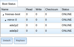
Fig. 4.3.2 Viewing the Status of the Operating System Device
If one of the operating system devices has a Status of OFFLINE, click the device to replace, select the new replacement device, and click Replace Disk to rebuild the boot mirror.
4.4. Advanced
is shown in Figure 4.4.1. The configurable settings are summarized in Table 4.4.1.
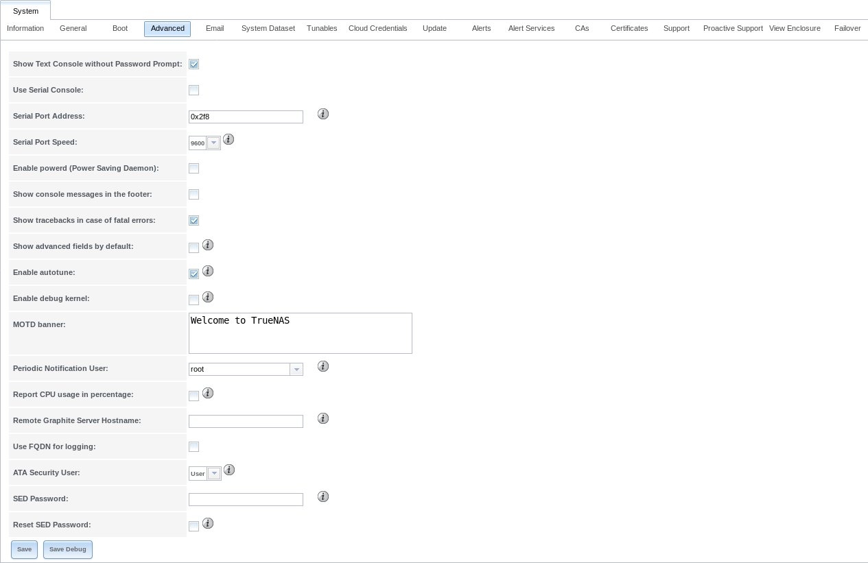
Fig. 4.4.1 Advanced Screen
| Setting | Value | Description |
|---|---|---|
| Show Text Console without Password Prompt | checkbox | Set for the system to immediately display the text console after booting. Unset to require logging into the system before the console menu is shown. |
| Use Serial Console | checkbox | Do not enable this option if the serial port is disabled. |
| Serial Port Address | string | Enter a serial port address in hex. |
| Serial Port Speed | drop-down menu | Select the speed used by the serial port. |
| Enable powerd (Power Saving Daemon) | checkbox | powerd(8) monitors the system state and sets the CPU frequency accordingly. |
| Show console messages in the footer | checkbox | Set to display console messages in real time at the bottom of the browser. Click the console to bring up a scrollable screen. Set Stop refresh in the scrollable screen to pause updating, and deselect the option to continue to watch the messages as they occur. |
| Show tracebacks in case of fatal errors | checkbox | Open a pop-up of diagnostic information when a fatal error occurs. |
| Show advanced fields by default | checkbox | Show Advanced Mode fields by default. |
| Enable autotune | checkbox | Enable an Autotune script which attempts to optimize the system based on the installed hardware. Warning: Autotuning is only used as a temporary measure and is not a permanent fix for system hardware issues. |
| Enable debug kernel | checkbox | Use a debug version of the kernel on the next boot. |
| MOTD banner | string | This message is shown when a user logs in with SSH. |
| Periodic Notification User | drop-down menu | Choose a user to receive security output emails. This output runs nightly but only sends email when the system reboots or encounters an error. |
| Report CPU usage in percentage | checkbox | Display CPU usage as percentages in Reporting. |
| Remote Graphite Server hostname | string | IP address or hostname of a remote server running Graphite. |
| Use FQDN for logging | checkbox | Include the Fully-Qualified Domain Name in logs to precisely identify systems with similar hostnames. |
| ATA Security User | drop-down menu | User passed to camcontrol security -u for unlocking Self-Encrypting Drives. Values are User or Master. |
| SED Password | string | Global password used to unlock Self-Encrypting Drives. |
| Reset SED Password | checkbox | Select to clear the Password for SED column of . |
Click the Save button after making any changes.
This tab also contains this button:
Save Debug: used to generate a text file of diagnostic information. After the debug data is collected, the system prompts for a location to save the compressed .tgz text file.
4.4.1. Autotune
TrueNAS® provides an autotune script which optimizes the system. The Enable autotune option in is enabled by default, so this script runs automatically. Leaving autotune enabled is recommended unless advised otherwise by an iXsystems support engineer.
If the autotune script adjusts any settings, the changed values appear in . While these values can be modified and overridden, speak to a support engineer first. Manual changes can have a negative impact on system performance. Note that deleting tunables that were created by autotune only affects the current session, as autotune-set tunables are recreated at boot.
For those who wish to see which checks are performed, the autotune
script is located in /usr/local/bin/autotune.
4.4.2. Self-Encrypting Drives
TrueNAS® version 11.1-U5 introduced Self-Encrypting Drive (SED) support.
These SED specifications are supported:
Legacy interface for older ATA devices. Not recommended for security-critical environments
TCG Opal 1 legacy specification
TCG OPAL 2 standard for newer consumer-grade devices
TCG Opalite is a reduced form of OPAL 2
TCG Pyrite Version 1 and Version 2 are similar to Opalite, but hardware encryption is removed. Pyrite provides a logical equivalent of the legacy ATA security for non-ATA devices. Only the drive firmware is used to protect the device.
Danger
Pyrite Version 1 SEDs do not have PSID support and can become unusable if the password is lost.
TCG Enterprise is designed for systems with many data disks. These SEDs do not have the functionality to be unlocked before the operating system boots.
See this Trusted Computing Group® and NVM Express® joint white paper for more details about these specifications.
TrueNAS® implements the security capabilities of camcontrol for legacy devices and sedutil-cli for TCG devices. When managing a SED from the command line, it is important to use sedutil-cli rather than camcontrol to access the full capabilities of the device. TrueNAS® provides the sedhelper wrapper script to ease SED administration from the command line.
By default, SEDs are not locked until the administrator takes ownership of them. Ownership is taken by explicitly configuring a global or per-device password in the TrueNAS® web interface and adding the password to the SEDs.
A password-protected SED protects the data stored on the device when the device is physically removed from the TrueNAS® system. This allows secure disposal of the device without having to first wipe the contents. Repurposing a SED on another system requires the SED password.
4.4.2.1. Deploying SEDs
Run sedutil-cli --scan in the Shell to detect and list devices. The second column of the results identifies the drive type:
- no indicates a non-SED device
- 1 indicates a legacy TCG OPAL 1 device
- 2 indicates a modern TCG OPAL 2 device
- L indicates a TCG Opalite device
- p indicates a TCG Pyrite 1 device
- P indicates a TCG Pyrite 2 device
- E indicates a TCG Enterprise device
Example:
root@truenas1:~ # sedutil-cli --scan
Scanning for Opal compliant disks
/dev/ada0  No  32GB SATA Flash Drive SFDK003L
/dev/ada1  No  32GB SATA Flash Drive SFDK003L
/dev/da0   No  HGST    HUS726020AL4210  A7J0
/dev/da1   No  HGST    HUS726020AL4210  A7J0
/dev/da10    E WDC     WUSTR1519ASS201  B925
/dev/da11    E WDC     WUSTR1519ASS201  B925
TrueNAS® supports setting a global password for all detected SEDs or setting individual passwords for each SED. Using a global password for all SEDs is strongly recommended to simplify deployment and avoid maintaining separate passwords for each SED.
4.4.2.1.1. Setting a global password for SEDs
Go to and enter the password. Record this password and store it in a safe place!
Now the SEDs must be configured with this password. Go to the
Shell and enter sedhelper setup password, where
password is the global password entered in
.
sedhelper ensures that all detected SEDs are properly configured to use the provided password:
root@truenas1:~ # sedhelper setup abcd1234
da9                  [OK]
da10                 [OK]
da11                 [OK]
Rerun sedhelper setup password every time a new SED is placed
in the system to apply the global password to the new SED.
4.4.2.1.2. Creating separate passwords for each SED
Go to . Click the confirmed SED, then Edit. Enter and confirm the password in the Password for SED and Confirm SED Password fields.
The . screen shows which disks have a configured SED password. The SED Password column shows a mark when the disk has a password. Disks that are not a SED or are unlocked using the global password are not marked in this column.
The SED must be configured to use the new password. Go to the
Shell and enter sedhelper setup --disk da1 password,
where da1 is the SED to configure and password is the created
password from
.
This process must be repeated for each SED and any SEDs added to the system in the future.
Danger
Remember SED passwords! If the SED password is lost, SEDs cannot be unlocked and their data is unavailable. While it is possible to specify the PSID number on the label of the device with sedutil-cli, doing so erases the contents of the device rather than unlock it. Always record SED passwords whenever they are configured or modified and store them in a secure place!
4.4.2.2. Check SED Functionality
When SED devices are detected during system boot, TrueNAS® checks for configured global and device-specific passwords.
Unlocking SEDs allows a pool to contain a mix of SED and non-SED devices. Devices with individual passwords are unlocked with their password. Devices without a device-specific password are unlocked using the global password.
To verify SED locking is working correctly, go to the Shell.
Enter sedutil-cli --listLockingRange 0 password dev/da1,
where da1 is the SED and password is the global or individual
password for that SED. The command returns ReadLockEnabled: 1,
WriteLockEnabled: 1, and LockOnReset: 1 for drives
with locking enabled:
root@truenas1:~ # sedutil-cli --listLockingRange 0 abcd1234 /dev/da9
Band[0]:
    Name:            Global_Range
    CommonName:      Locking
    RangeStart:      0
    RangeLength:     0
    ReadLockEnabled: 1
    WriteLockEnabled:1
    ReadLocked:      0
    WriteLocked:     0
    LockOnReset:     1
4.5. Email
An automatic script sends a nightly email to the root user account containing important information such as the health of the disks. Alert events are also emailed to the root user account. Problems with Scrubs are reported separately in an email sent at 03:00AM.
Note
S.M.A.R.T. reports are mailed separately to the address configured in that service.
The administrator typically does not read email directly on the TrueNAS® system. Instead, these emails are usually sent to an external email address where they can be read more conveniently. It is important to configure the system so it can send these emails to the administrator’s remote email account so they are aware of problems or status changes.
The first step is to set the remote address where email will be sent. Select , click on root to highlight that user, then click Modify User. In the E-mail field, enter the email address on the remote system where email is to be sent, like admin@example.com. Click OK to save the settings.
Additional configuration is performed with , shown in Figure 4.5.1.
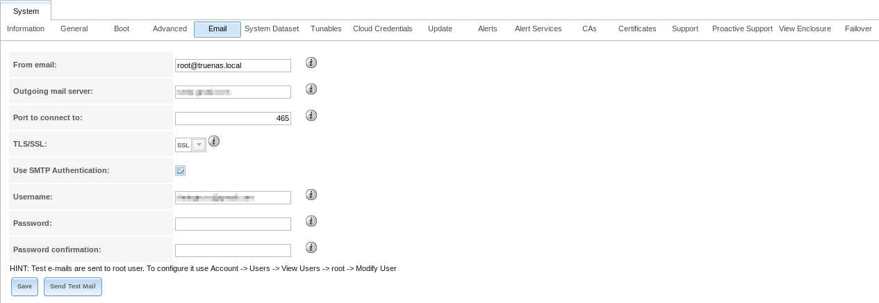
Fig. 4.5.1 Email Screen
| Setting | Value | Description |
|---|---|---|
| From email | string | The envelope From address shown in the email. This can be set to make filtering mail
on the receiving system easier. The friendly name is set like this:
Friendly Name <address@example.com> |
| Outgoing mail server | string or IP address | Hostname or IP address of SMTP server used for sending this email. |
| Port to connect to | integer | SMTP port number. Typically 25, 465 (secure SMTP), or 587 (submission). |
| TLS/SSL | drop-down menu | Choose an encryption type. Choices are Plain, SSL, or TLS |
| Use SMTP Authentication | checkbox | Enable or disable SMTP AUTH using PLAIN SASL. If enabled, enter the required Username and Password. |
| Username | string | Enter the SMTP username if the SMTP server requires authentication. |
| Password | string | Enter the SMTP password if the SMTP server requires authentication. Only plain text characters (7-bit ASCII) are allowed in passwords. UTF or composed characters are not allowed. |
| Password Confirmation | string | Confirm the SMTP password. |
Click the Send Test Mail button to verify that the configured email settings are working. If the test email fails, double-check that the E-mail field of the root user is correctly configured by clicking the Modify User button for the root account in .
Configuring email for TLS/SSL email providers is described in Are you having trouble getting FreeNAS to email you in Gmail?.
Note
The TrueNAS® user who receives periodic email is set in the Periodic Notification User field in .
4.6. System Dataset
, shown in Figure 4.6.1, is used to select the pool which contains the persistent system dataset. The system dataset stores debugging core files and Samba4 metadata such as the user or group cache and share level permissions. If the TrueNAS® system is configured to be a Domain Controller, all of the domain controller state is stored there as well, including domain controller users and groups.
Note
When the system dataset is moved, a new dataset is created and set active. The old dataset is intentionally not deleted by the system because the move might be transient or the information in the old dataset might be useful for later recovery.
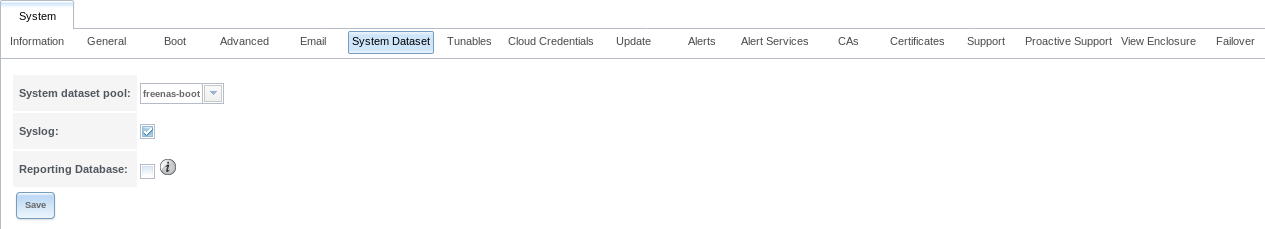
Fig. 4.6.1 System Dataset Screen
Use the System dataset pool drop-down menu to select the volume (pool) to contain the system dataset. The system dataset can be moved to unencrypted volumes (pools) or encrypted volumes which do not have passphrases. If the system dataset is moved to an encrypted volume, that volume is no longer allowed to be locked or have a passphrase set.
Moving the system dataset also requires rebooting the passive storage controller for High Availability TrueNAS® systems and restarting the SMB service. A dialog warns that the SMB service must be restarted, causing a temporary outage of any active SMB connections.
System logs can also be stored on the system dataset. Storing this
information on the system dataset is recommended when large amounts of
data is being generated and the system has limited memory or a limited
capacity operating system device. Set Syslog to store system logs on the
system dataset. Leave unset to store system logs in /var on the
operating system device.
Set Reporting Database to store Reporting data on the
system dataset. Leave unset to create a /temp disk in RAM to
store the reporting database.
Click Save to save changes.
If the pool storing the system dataset is changed at a later time, TrueNAS® migrates the existing data in the system dataset to the new location.
Note
Depending on configuration, the system dataset can occupy a large amount of space and receive frequent writes. Do not put the system dataset on a flash drive or other media with limited space or write life.
4.7. Tunables
can be used to manage:
- FreeBSD sysctls: a sysctl(8) makes changes to the FreeBSD kernel running on a TrueNAS® system and can be used to tune the system.
- FreeBSD loaders: a loader is only loaded when a FreeBSD-based system boots and can be used to pass a parameter to the kernel or to load an additional kernel module such as a FreeBSD hardware driver.
- FreeBSD rc.conf options:
rc.conf(5)
is used to pass system configuration options to the system startup
scripts as the system boots. Since TrueNAS® has been optimized for
storage, not all of the services mentioned in rc.conf(5) are
available for configuration. Note that in TrueNAS®, customized
rc.conf options are stored in
/tmp/rc.conf.freenas.
Warning
Adding a sysctl, loader, or rc.conf option is an
advanced feature. A sysctl immediately affects the kernel running
the TrueNAS® system and a loader could adversely affect the ability
of the TrueNAS® system to successfully boot.
Do not create a tunable on a production system unless it is
understood and ramifications have been tested for that change.
Since sysctl, loader, and rc.conf values are specific to the kernel parameter to be tuned, the driver to be loaded, or the service to configure, descriptions and suggested values can be found in the man page for the specific driver and in many sections of the FreeBSD Handbook.
To add a loader, sysctl, or rc.conf option, go to
,
to access the screen shown in
Figure 4.7.1.
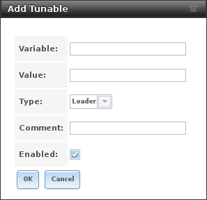
Fig. 4.7.1 Adding a Tunable
Table 4.7.1 summarizes the options when adding a tunable.
| Setting | Value | Description |
|---|---|---|
| Variable | string | The name of the sysctl or driver to load. |
| Value | integer or string | Set a value for the Variable. Refer to the man page for the specific driver or the FreeBSD Handbook for suggested values. |
| Type | drop-down menu | Choices are Loader, rc.conf, or Sysctl. |
| Comment | string | Enter a userful description of this tunable. |
| Enabled | checkbox | Unset this option to disable the tunable without deleting it. |
Note
As soon as a Sysctl is added or edited, the running kernel changes that variable to the value specified. However, when a Loader or rc.conf value is changed, it does not take effect until the system is rebooted. Regardless of the type of tunable, changes persist at each boot and across upgrades unless the tunable is deleted or the Enabled option is deselected.
Any added tunables are listed in . To change the value of an existing tunable, click its Edit button. To remove a tunable, click its Delete button.
Restarting the TrueNAS® system after making sysctl changes is recommended. Some sysctls only take effect at system startup, and restarting the system guarantees that the setting values correspond with what is being used by the running system.
The web interface does not display the sysctls that are pre-set when TrueNAS® is installed. TrueNAS® 11.2 ships with the sysctls set:
kern.metadelay=3
kern.dirdelay=4
kern.filedelay=5
kern.coredump=1
net.inet.carp.preempt=1
debug.ddb.textdump.pending=1
vfs.nfsd.tcpcachetimeo=300
vfs.nfsd.tcphighwater=150000
vfs.zfs.vdev.larger_ashift_minimal=0
net.inet.carp.senderr_demotion_factor=0
net.inet.carp.ifdown_demotion_factor=0
Do not add or edit these default sysctls as doing so may render the system unusable.
The web interface does not display the loaders that are pre-set when TrueNAS® is installed. TrueNAS® 11.2 ships with these loaders set:
autoboot_delay="2"
loader_logo="truenas-logo"
loader_menu_title="Welcome to TrueNAS"
loader_brand="truenas-brand"
loader_version=" "
kern.cam.boot_delay="10000"
debug.debugger_on_panic=1
debug.ddb.textdump.pending=1
hw.hptrr.attach_generic=0
ispfw_load="YES"
freenas_sysctl_load="YES"
hint.isp.0.topology="nport-only"
hint.isp.1.topology="nport-only"
hint.isp.2.topology="nport-only"
hint.isp.3.topology="nport-only"
module_path="/boot/kernel;/boot/modules;/usr/local/modules"
net.inet6.ip6.auto_linklocal="0"
net.inet.tcp.reass.maxqueuelen=1436
vfs.zfs.vol.mode=2
kern.geom.label.disk_ident.enable=0
kern.geom.label.ufs.enable=0
kern.geom.label.ufsid.enable=0
kern.geom.label.reiserfs.enable=0
kern.geom.label.ntfs.enable=0
kern.geom.label.msdosfs.enable=0
kern.geom.label.ext2fs.enable=0
hint.ahciem.0.disabled="1"
hint.ahciem.1.disabled="1"
kern.msgbufsize="524288"
hw.mfi.mrsas_enable="1"
hw.usb.no_shutdown_wait=1
vfs.nfsd.fha.write=0
vfs.nfsd.fha.max_nfsds_per_fh=32
kern.ipc.nmbclusters="262144"
kern.hwpmc.nbuffers="4096"
kern.hwpmc.nsamples="4096"
hw.memtest.tests="0"
vfs.zfs.trim.enabled="0"
kern.cam.ctl.ha_mode=2
hint.ntb_hw.0.config="ntb_pmem:1:4:0,ntb_transport"
hint.ntb_transport.0.config=":3"
hw.ntb.msix_mw_idx="-1"
Do not add or edit the default tunables. Changing the default tunables can make the system unusable.
The ZFS version used in 11.2 deprecates these tunables:
kvfs.zfs.write_limit_override
vfs.zfs.write_limit_inflated
vfs.zfs.write_limit_max
vfs.zfs.write_limit_min
vfs.zfs.write_limit_shift
vfs.zfs.no_write_throttle
After upgrading from an earlier version of TrueNAS®, these tunables are automatically deleted. Please do not manually add them back.
4.8. Cloud Credentials
TrueNAS® can use cloud services for features like Cloud Sync. The credentials to provide secure connections with cloud services are entered here. Amazon S3, Backblaze B2, Box, Dropbox, FTP, Google Cloud Storage, Google Drive, HTTP, hubiC, Mega, Microsoft Azure Blob Storage, Microsoft OneDrive, pCloud, SFTP, WebDAV, and Yandex are supported.
Note
The hubiC cloud service has suspended creation of new accounts.
Warning
Cloud Credentials are stored in encrypted form. To be able to restore Cloud Credentials from a saved configuration, Export Password Secret Seed must be set when saving that configuration.
Select to see the screen shown in Figure 4.8.1.
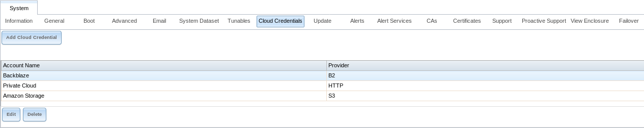
Fig. 4.8.1 Cloud Credentials List
The list shows the Account Name and Provider for each credential. There are options to Edit and Delete a credential after selecting it. Click Add Cloud Credential to display the dialog shown in Figure 4.8.2.
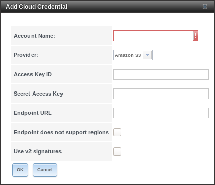
Fig. 4.8.2 Adding Cloud Credentials
Amazon S3 options are shown by default. Enter a descriptive and unique name for the cloud credential in the Account Name field, then select a Provider. The remaining options vary by provider, and are shown in Table 4.8.1.
| Provider | Setting | Description |
|---|---|---|
| Amazon S3 | Access Key ID | Enter the Amazon Web Services Key ID. This is found on Amazon AWS by going through My account –> Security Credentials –> Access Keys. |
| Amazon S3 | Secret Access Key | Enter the Amazon Web Services password. If the Secret Access Key cannot be found or remembered, go to My Account –> Security Credentials –> Access Keys and create a new key pair. |
| Amazon S3 | Endpoint URL | Leave blank when using AWS as the available buckets are fetched dynamically. Only enter an Endpoint URL if using custom S3 API. URL general format: bucket-name.s3-website-region.amazonaws.com. Refer to the AWS Documentation for a list of Simple Storage Service Websites Endpoints. |
| Amazon S3 | Endpoint does not support regions | Skip automatic detection of the Endpoint URL region. Set this when configuring a custom Endpoint URL. |
| Amazon S3 | Use v2 signatures | Force using Signature Version 2 to sign API requests. Set this when configuring a custom Endpoint URL. |
| Backblaze B2 | Account ID or Application Key ID, Application Key | Enter the Account ID and Master Application Key for the Backblaze B2 account. These are visible after logging into the account, clicking Buckets, and clicking Show Account ID and Application Key. An Application Key with limited permissions can be used in place of the Account ID. Create a new Application Key, enter the key string in the Application Key field, and replace the Account ID with the keyID. |
| Box | Automatic config, OAuth Client ID, OAuth Client Secret, Access Token | Configured with Open Authentication. |
| Dropbox | Automatic config OAuth Client ID, OAuth Client Secret, Access Token | Configured with Open Authentication. The access token can be manually created by going to the Dropbox App Console. After creating an app, go to Settings and click Generate under the Generated access token field. |
| FTP | Host, Port | Enter the FTP host and port. |
| FTP | Username, Password | Enter the FTP username and password. |
| Google Cloud Storage | Service Account | Browse to the location of the saved Google Cloud Storage key and select it. |
| Google Drive | Automatic config, OAuth Client ID, OAuth Client Secret, Access Token, Team Drive ID | OAuth Client ID, OAuth Client Secret, and Access Token are configured with Open Authentication. The Team Drive ID is only used when connecting to a Team Drive. The ID is also the ID of the top level folder of the Team Drive. |
| HTTP | URL | Enter the URL. |
| hubiC | Access Token | Enter the access token. See the Hubic guide for instructions to obtain an access token. |
| Mega | Username, Password | Enter the Mega username and password. |
| Microsoft Azure Blob Storage | Account Name, Account Key | Enter the Azure Blob Storage account name and key. |
| Microsoft OneDrive | Automatic config, OAuth Client ID, OAuth Client Secret, Access Token, Drive Account Type, Drive ID | OAuth Client ID, OAuth Client Secret, and Access Token are configured with Open Authentication. Choose the account type: PERSONAL, BUSINESS, or SharePoint DOCUMENT_LIBRARY. To find the Drive ID, log in to the OneDrive account and copy the string that
appears in the browser address bar after |
| pCloud | Automatic config, OAuth Client ID, OAuth Client Secret, Access Token | Configured with Open Authentication. |
| SFTP | Host, Port | Enter the SFTP host and port. |
| SFTP | Username, Password, PEM-encoded private key file path | Enter the SFTP username, password, and PEM-encoded private key file path. |
| WebDAV | URL, WebDAV Service | Enter URL and use the dropdown to select the WebDAV service. |
| WebDAV | Username, Password | Enter the username and password. |
| Yandex | Automatic config, OAuth Client ID, OAuth Client Secret, Access Token | Configured with Open Authentication. |
For Amazon S3, Access Key and Secret Key are shown. These values are found on the Amazon AWS website by clicking on the account name, then My Security Credentials and Access Keys (Access Key ID and Secret Access Key). Copy the Access Key value to the TrueNAS® Cloud Credential Access Key field, then enter the Secret Key value saved when the key pair was created. If the Secret Key value is unknown, a new key pair can be created on the same Amazon screen.
The Google Cloud Storage JSON Service Account Key is found on the Google Cloud Platform Console.
Open Authentication (OAuth) is used with some cloud providers. These providers have an Automatic config link that opens a dialog to log in to that provider and fill the TrueNAS® OAuth Client ID, OAuth Client Secret, and Access Token fields with valid credentials.
More details about individual Provider settings are available in the rclone documentation.
4.9. Update
TrueNAS® has an integrated update system to make it easy to keep up to date.
4.9.1. Preparing for Updates
An update usually takes between thirty minutes and an hour. A reboot is required after the update, so it is recommended to schedule updates during a maintenance window, allowing two to three hours to update, test, and possibly roll back if issues appear. On very large systems, a proportionally longer maintenance window is recommended.
For individual support during an upgrade, open a ticket with or call iXsystems Support to schedule an upgrade. Scheduling at least two days in advance of a planned upgrade gives time to make sure a specialist is available for assistance.
Updates from older versions of TrueNAS® before 9.3 must be scheduled with iXsystems Support.
The update process will not proceed unless there is enough free space in the boot pool for the new update files. If a space warning is shown, use Boot to remove unneeded boot environments.
Operating system updates only modify the operating system devices and do not affect end-user data on storage drives.
Available ZFS version upgrades are indicated by an Alert in the graphical user interface. However, upgrading the ZFS version on storage drives is not recommended until after verifying that rolling back to previous versions of the operating system will not be necessary, and that interchanging the devices with some other system using an older ZFS version is not needed. After a ZFS version upgrade, the storage devices will not be accessible by older versions of TrueNAS®.
4.9.2. Updates and Trains
Cryptographically signed update files are used to update TrueNAS®. Update files provide flexibility in deciding when to upgrade the system. Boot environments make it possible to test an update.
Figure 4.9.1 shows an example of the screen.
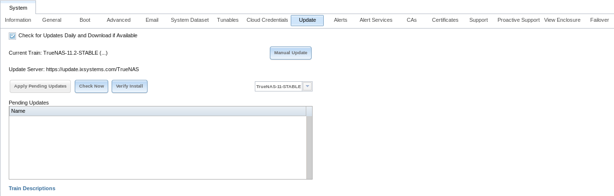
Fig. 4.9.1 Update Options
The system checks daily for updates and downloads an update if one is available. An alert is issued when a new update becomes available. The automatic check and download of updates can be disabled by unsetting Check for Updates Daily and Download if Available.
This screen lists the URL of the official update server in case that information is needed in a network with outbound firewall restrictions. It also shows which software branch, or train, is being tracked for updates.
Several trains are available for updates. Update trains are labeled with a numeric version and a short description.
These update trains are available:
For Production Use
TrueNAS-11-STABLE (Recommended)
After new fixes and features have been tested as production-ready, they are added to this train. Following this train and applying any pending updates from it is recommended.
Legacy Versions
TrueNAS-9.10-STABLE
Maintenance-only updates for the previous branch of TrueNAS®.
TrueNAS-9.3-STABLE
Maintenance-only updates for the older 9.3 branch of TrueNAS®. Use this train only at the recommendation of an iX support engineer.
The Verify Install button verifies that the operating system files in the current installation do not have any inconsistencies. If any problems are found, a pop-up menu lists the files with checksum mismatches or permission errors.
4.9.3. Checking for Updates
To see if any updates are available, click the Check Now button. Any available updates are listed.
4.9.4. Applying Updates
Make sure the system is in a low-usage state as described above in Preparing for Updates.
Click the OK button to immediately download and install an update. Be aware that some updates automatically reboot the system after they are applied.
Warning
Each update creates a boot environment. If the update process needs more space, it attempts to remove old boot environments. Boot environments marked with the Keep attribute as shown in Boot will not be removed. If space for a new boot environment is not available, the upgrade fails. Space on the boot device can be manually freed using . Review the boot environments and remove the Keep attribute or delete any boot environments that are no longer needed.
During the update process a progress dialog appears. Do not interrupt the update until it completes.
Updates can also be downloaded and applied later. To do so, unset the Apply updates after downloading option before pressing OK. In this case, this screen closes after updates are downloaded. Downloaded updates are listed in the Pending Updates section of the screen shown in Figure 4.9.1. When ready to apply the previously downloaded updates, click the Apply Pending Updates button. Remember that the system reboots after the updates are applied.
Warning
After updates have completed, reboot the system. Configuration changes made after an update but before that final reboot will not be saved.
4.9.5. Manual Updates
Updates can be manually downloaded as a file with a name ending in
-manual-update-unsigned.tar. Find a .tar
file with the desired version at
https://download.freenas.org/.
After obtaining the update file, click Manual Update and
choose a location to temporarily store the file on the TrueNAS® system.
Use the file browser to locate the update file, then click
Apply Update.
There is also an option to back up the system configuration before updating. Click Click here and select any options to export in the configuration file. Click OK to open a popup window to save the system configuration. A progress dialog is displayed during the update. Do not interrupt the update.
Tip
Manual updates cannot be used to upgrade from older major versions.
4.9.6. Updating from the Shell
Updates can also be performed from the Shell with an update
file. Make the update file available by copying it to the TrueNAS®
system, then run the update program, giving it the path to the file:
freenas-update update_file.
4.9.7. Updating an HA System
If the TrueNAS® array has been configured for High Availability (HA), the update process must be started on the active node. Once the update is complete, the standby node will automatically reboot. Wait for it to come back up by monitoring the remote console or the graphical administrative interface of the standby node.
After the standby node has finished booting, it is important to perform a failover by rebooting the current active node. This action tells the standby node to import the current configuration and restart services.
Once the previously active node comes back up as a standby node, use to apply the update on the current active node, which was previously the passive node. Once complete, the now standby node will reboot a second time.
4.9.8. If Something Goes Wrong
If an update fails, an alert is issued and the details are written to
/data/update.failed.
To return to a previous version of the operating system, physical or
IPMI access to the TrueNAS® console is required. Reboot the system and
press the space bar when the boot menu appears, pausing the boot.
Select an entry with a date prior to the update, then press
Enter to boot into that version of the operating system before
the update was applied.
4.9.9. Upgrading a ZFS Pool
In TrueNAS®, ZFS pools can be upgraded from the graphical administrative interface.
Before upgrading an existing ZFS pool, be aware of these caveats first:
- the pool upgrade is a one-way street, meaning that if you change your mind you cannot go back to an earlier ZFS version or downgrade to an earlier version of the software that does not support those ZFS features.
- before performing any operation that may affect the data on a storage disk, always back up all data first and verify the integrity of the backup. While it is unlikely that the pool upgrade will affect the data, it is always better to be safe than sorry.
- upgrading a ZFS pool is optional. Do not upgrade the pool if the the possibility of reverting to an earlier version of TrueNAS® or repurposing the disks in another operating system that supports ZFS is desired. It is not necessary to upgrade the pool unless the end user has a specific need for the newer ZFS Feature Flags. If a pool is upgraded to the latest feature flags, it will not be possible to import that pool into another operating system that does not yet support those feature flags.
To perform the ZFS pool upgrade, go to and highlight the volume (ZFS pool) to upgrade. Click the “Up Arrow” (Upgrade) button as shown in Figure 4.9.2.
Note
If the “Up Arrow” (Upgrade) button does not appear, the pool is already at the latest feature flags and does not need to be upgraded.
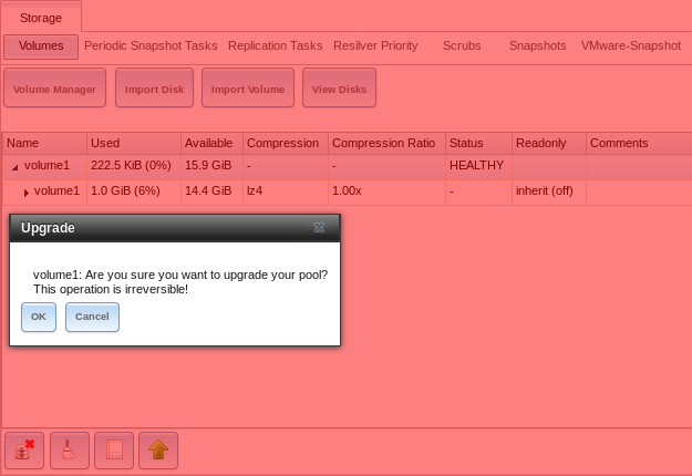
Fig. 4.9.2 Upgrading a ZFS Pool
The warning serves as a reminder that a pool upgrade is not reversible. Click OK to proceed with the upgrade.
The upgrade itself only takes a few seconds and is non-disruptive. It is not necessary to stop any sharing services to upgrade the pool. However, it is best to upgrade when the pool is not being heavily used. The upgrade process will suspend I/O for a short period, but is nearly instantaneous on a quiet pool.
4.10. Alerts
displays the default notification frequency for each type of Alert. An example is seen in Figure 4.10.1.
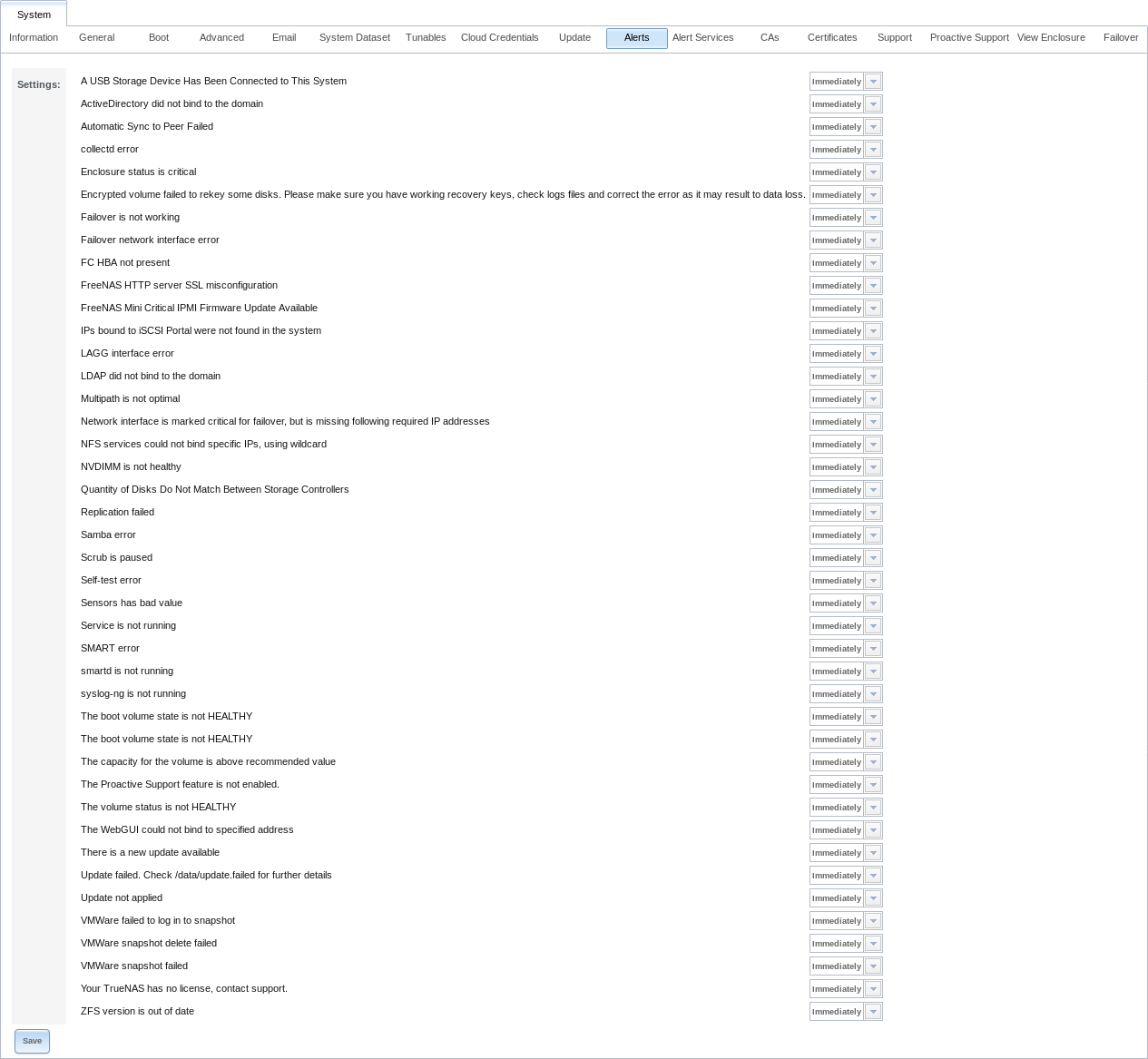
Fig. 4.10.1 Configure Alert Notification Frequency
To change the notification frequency of an alert, click its drop-down menu and select IMMEDIATELY, HOURLY, DAILY, or NEVER.
To configure where to send alerts, use Alert Services.
4.11. Alert Services
TrueNAS® can use a number of methods to notify the administrator of system events that require attention. These events are system Alerts marked WARN or CRITICAL.
Currently available alert services:
Warning
These alert services might use a third party commercial vendor not directly affiliated with iXsystems. Please investigate and fully understand that vendor’s pricing policies and services before using their alert service. iXsystems is not responsible for any charges incurred from the use of third party vendors with the Alert Services feature.
Select to show the Alert Services screen. Click Add Service to display the dialog shown in Figure 4.11.1.
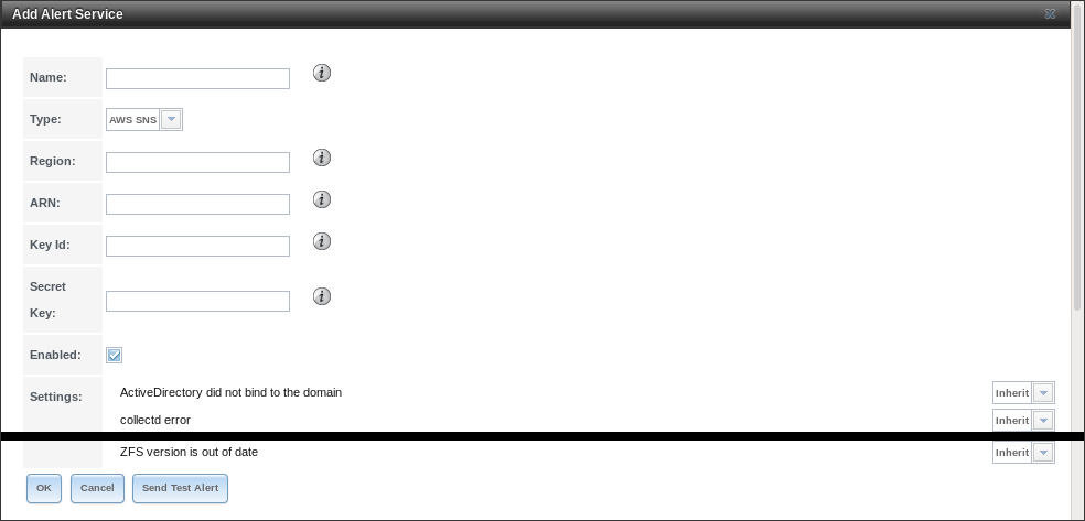
Fig. 4.11.1 Add Alert Service
Enter a specific Name for the new alert service. The Type drop-down menu is used to pick a specific alert service. The Settings area allows configuring when specific alerts will trigger. Options are to Inherit the setting from Alerts or generate the alert Immediately, Hourly, Daily, or Never. The fields shown in the rest of the dialog change to those required by that service.
Click Send Test Alert to test the current selections. Click OK to save the new alert service. To send a test alert using an existing service, highlight an alert entry, click Edit, and click Send Test Alert.
System alerts marked WARN or CRITICAL are sent to each alert service that has been configured and enabled.
Alert services are deleted from this list by clicking them and then clicking Delete at the bottom of the window. To disable an alert service, click Edit and unset Enabled.
4.12. CAs
TrueNAS® can act as a Certificate Authority (CA). When encrypting SSL or TLS connections to the TrueNAS® system, either import an existing certificate, or create a CA on the TrueNAS® system, then create a certificate. This certificate will appear in the drop-down menus for services that support SSL or TLS.
For secure LDAP, the public key of an existing CA is imported with Import CA, or a new CA created on the TrueNAS® system and used on the LDAP server also.
Figure 4.12.1 shows the screen after clicking .
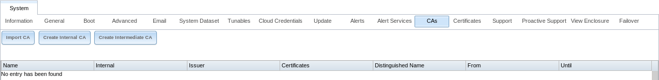
Fig. 4.12.1 Initial CA Screen
If the organization already has a CA, the CA certificate and key can be imported. Click the Import CA button to open the configuration screen shown in Figure 4.12.2. The configurable options are summarized in Table 4.12.1.
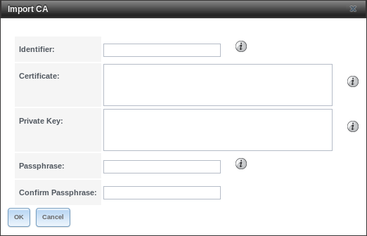
Fig. 4.12.2 Importing a CA
| Setting | Value | Description |
|---|---|---|
| Identifier | string | Enter a descriptive name for the CA using only alphanumeric,
underscore (_), and dash (-) characters. |
| Certificate | string | Paste in the certificate for the CA. |
| Private Key | string | If there is a private key associated with the Certificate, paste it here. Private keys must be at least 1024 bits long. |
| Passphrase | string | If the Private Key is protected by a passphrase, enter it here and repeat it in the Confirm Passphrase field. |
To create a new CA, first decide if it will be the only CA which will sign certificates for internal use or if the CA will be part of a certificate chain.
To create a CA for internal use only, click the Create Internal CA button which will open the screen shown in Figure 4.12.3.
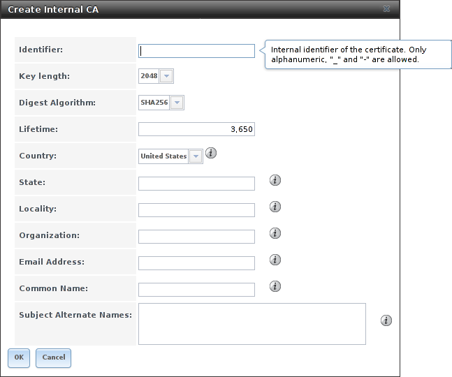
Fig. 4.12.3 Creating an Internal CA
The configurable options are described in Table 4.12.2. When completing the fields for the certificate authority, supply the information for the organization.
| Setting | Value | Description |
|---|---|---|
| Identifier | string | Enter a descriptive name for the CA using only alphanumeric,
underscore (_), and dash (-) characters. |
| Key Length | drop-down menu | For security reasons, a minimum of 2048 is recommended. |
| Digest Algorithm | drop-down menu | The default is acceptable unless the organization requires a different algorithm. |
| Lifetime | integer | The lifetime of the CA is specified in days. |
| Country | drop-down menu | Select the country for the organization. |
| State | string | Enter the state or province of the organization. |
| Locality | string | Enter the location of the organization. |
| Organization | string | Enter the name of the company or organization. |
| Email Address | string | Enter the email address for the person responsible for the CA. |
| Common Name | string | Enter the fully-qualified hostname (FQDN) of the system. The Common Name must be unique within a certificate chain. |
| Subject Alternate Names | string | Multi-domain support. Enter additional domain names and separate them with a space. |
To create an intermediate CA which is part of a certificate chain, click Create Intermediate CA. This screen adds one more option to the screen shown in Figure 4.12.3:
- Signing Certificate Authority: this drop-down menu is used to specify the root CA in the certificate chain. This CA must first be imported or created.
Imported or created CAs are added as entries in . The columns in this screen indicate the name of the CA, whether it is an internal CA, whether the issuer is self-signed, the number of certificates that have been issued by the CA, the distinguished name of the CA, the date and time the CA was created, and the date and time the CA expires.
Clicking the entry for a CA causes these buttons to become available:
- Sign CSR: used to sign internal Certificate Signing Requests created using .
- Export Certificate: prompts to browse to the location to save a copy of the CA X.509 certificate on the computer being used to access the TrueNAS® system.
- Export Private Key: prompts to browse to the location to save a copy of the CA private key on the computer being used to access the TrueNAS® system. This option only appears if the CA has a private key.
- Delete: prompts for confirmation before deleting the CA.
4.13. Certificates
TrueNAS® can import existing certificates, create new certificates, and issue certificate signing requests so that created certificates can be signed by the CA which was previously imported or created in CAs.
Figure 4.13.1 shows the initial screen after clicking .
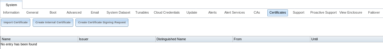
Fig. 4.13.1 Initial Certificates Screen
To import an existing certificate, click Import Certificate to open the configuration screen shown in Figure 4.13.2. When importing a certificate chain, paste the primary certificate, followed by any intermediate certificates, followed by the root CA certificate.
On TrueNAS® High Availability (HA) systems, the imported certificate must include the IP addresses or DNS hostnames of both nodes and the CARP virtual IP address. These IP addresses or DNS hostnames can be placed in the Subject Alternative Name (SAN) x509 extension field of the certificate being imported.
The configurable options are summarized in Table 4.13.1.
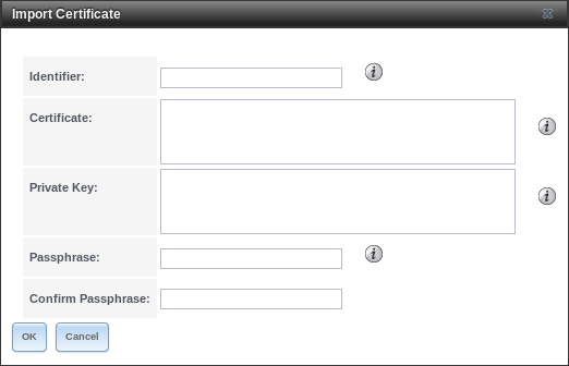
Fig. 4.13.2 Importing a Certificate
| Setting | Value | Description |
|---|---|---|
| Identifier | string | Enter a descriptive name for the certificate using only alphanumeric,
underscore (_), and dash (-) characters. |
| Certificate | string | Paste the contents of the certificate. |
| Private Key | string | Paste the private key associated with the certificate. Private keys must be at least 1024 bits long. |
| Passphrase | string | If the private key is protected by a passphrase, enter it here and repeat it in the Confirm Passphrase field. |
To create a new self-signed certificate, click the Create Internal Certificate button to see the screen shown in Figure 4.13.3. The configurable options are summarized in Table 4.13.2. When completing the fields for the certificate authority, use the information for the organization. Since this is a self-signed certificate, use the CA that was imported or created with CAs as the signing authority.
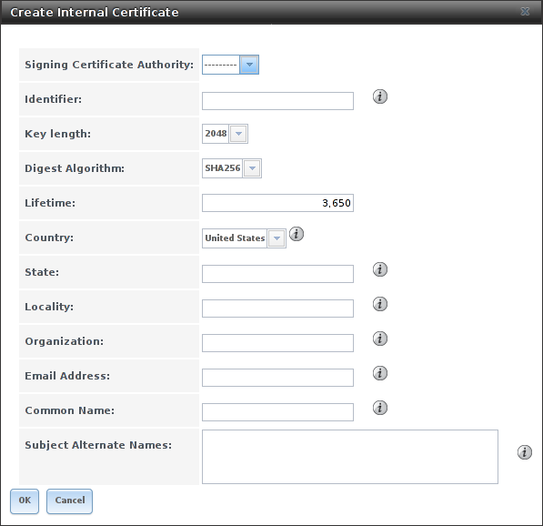
Fig. 4.13.3 Creating a New Certificate
| Setting | Value | Description |
|---|---|---|
| Signing Certificate Authority | drop-down menu | Select the CA which was previously imported or created using CAs. |
| Identifier | string | Enter a descriptive name for the certificate using only alphanumeric,
underscore (_), and dash (-) characters. |
| Key Length | drop-down menu | For security reasons, a minimum of 2048 is recommended. |
| Digest Algorithm | drop-down menu | The default is acceptable unless the organization requires a different algorithm. |
| Lifetime | integer | The lifetime of the certificate is specified in days. |
| Country | drop-down menu | Select the country for the organization. |
| State | string | State or province for the organization. |
| Locality | string | Location of the organization. |
| Organization | string | Name of the company or organization. |
| Email Address | string | Email address for the person responsible for the CA. |
| Common Name | string | Enter the fully-qualified hostname (FQDN) of the system. The Common Name must be unique within a certificate chain. |
| Subject Alternate Names | string | Multi-domain support. Enter additional domain names and separate them with a space. |
If the certificate is signed by an external CA, such as Verisign, instead create a certificate signing request. To do so, click Create Certificate Signing Request. A screen like the one in Figure 4.13.3 opens, but without the Signing Certificate Authority field.
Certificates that are imported, self-signed, or for which a certificate signing request is created are added as entries to . In the example shown in Figure 4.13.4, a self-signed certificate and a certificate signing request have been created for the fictional organization My Company. The self-signed certificate was issued by the internal CA named My_Company and the administrator has not yet sent the certificate signing request to Verisign so that it can be signed. Once that certificate is signed and returned by the external CA, it should be imported using Import Certificate so it is available as a configurable option for encrypting connections.
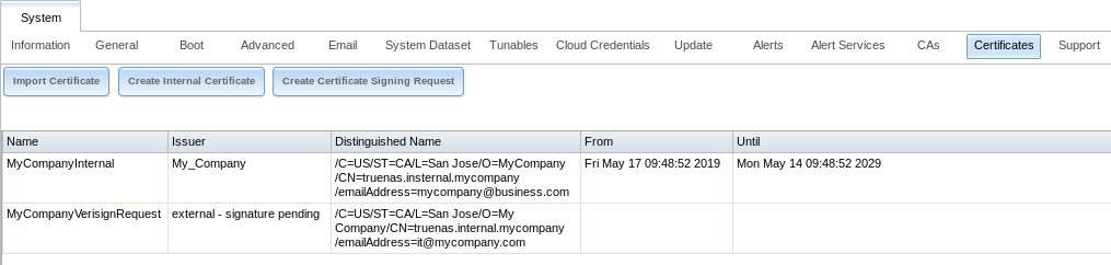
Fig. 4.13.4 Managing Certificates
Clicking an entry activates these configuration buttons:
- View: use this option to view the contents of an existing certificate or to edit the Identifier.
- Export Certificate saves a copy of the certificate or certificate signing request to the system being used to access the TrueNAS® system. For a certificate signing request, send the exported certificate to the external signing authority so that it can be signed.
- Export Private Key saves a copy of the private key associated with the certificate or certificate signing request to the system being used to access the TrueNAS® system.
- Edit shows the details for an existing certificate signing request and includes an area to paste a Certificate.
- Delete is used to delete a certificate or certificate signing request.
4.14. Support
The TrueNAS® Support tab, shown in Figure 4.14.1, is used to view or update the system license information. It also provides a built-in ticketing system for generating support requests.
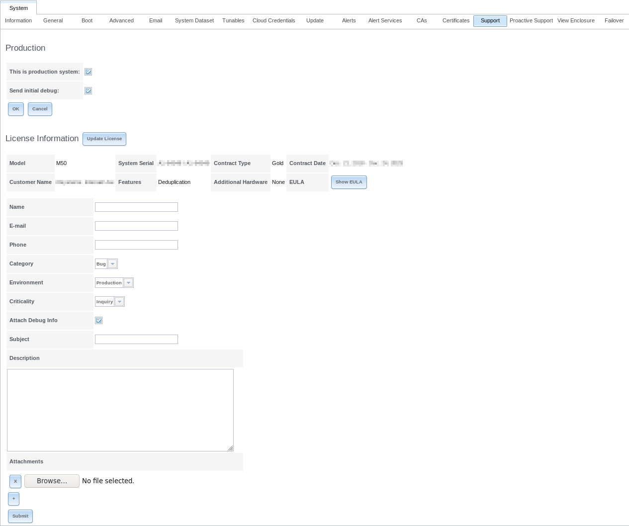
Fig. 4.14.1 Support Tab
This example shows a system that is used in production with an initial debug sent to iXsystems Support.
The system has a valid license which indicates the hardware model, system serial number, support contract type, licensed period, customer name, licensed features, additional supported hardware, and a Show EULA button.
If the license expires or additional hardware, features, or contract type are required, contact an iXsystems support engineer. After a new license string has been provided, click the Update License button, paste in the new license, and click OK. The new details will be displayed.
To generate a support ticket, fill in the fields:
Name is the name of the person the iXsystems Support Representative should contact to assist with the issue.
E-mail is the email address of the person to contact.
Phone is the phone number of the person to contact.
Category is a drop-down menu to select whether the ticket is to report a software bug, report a hardware failure, ask for assistance in installing or configuring the system, or request assistance in diagnosing a performance bottleneck.
Environment is a drop-down menu to indicate the role of the affected system.
| Environment | Description |
|---|---|
| Production | This is a production system in daily use. |
| Staging | The system is being prepared for production. |
| Test | This system is only being used for testing purposes. |
| Prototyping | The system is unique. It is likely to be a proof of concept. |
| Initial Deployment/ | This is a new system being prepared for deployment into production. |
- Criticality is a drop-down menu to indicate the criticality level. Choices are Inquiry, Loss of Functionality, or Total Down.
- Attach Debug Info leaving this option selected is recommended so an overview of the system hardware and configuration to be automatically generated and included with the ticket.
- Subject is a descriptive title for the ticket.
- Description is a one- to three-paragraph summary of the issue that describes the problem, and if applicable, steps to reproduce it.
- Attachments is an optional field where configuration files or screenshots of any errors or tracebacks can be included. Click the + button to add more attachments.
Click Submit to generate and send the support ticket to iXsystems. This process can take several minutes while information is collected and sent.
After the new ticket is created, the URL is shown for updating with more information. An iXsystems Support account is required to view the ticket. Click the URL to log in or register with the support portal. Use the same u-mail address submitted with the ticket when registering.
4.15. Proactive Support
The Proactive Support feature can notify iXsystems by email when hardware conditions on the system require attention.
Note
The fields on this tab are only enabled for Silver and Gold support coverage level customers. Please contact iXsystems for information on upgrading from other support levels.
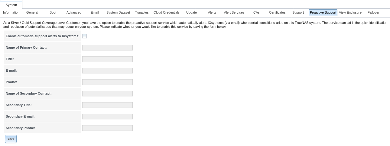
Fig. 4.15.1 Proactive Support Tab
The Proactive Support fields are:
- Enable automatic support alerts to iXsystems allows enabling or disabling Proactive Support emails to iXsystems. It is recommended to enable this automatic reporting.
- Name of Primary Contact is the name of the first person to be contacted by iXsystems Support to assist with issues.
- Title is the title of the primary contact person.
- E-mail is the email address of the primary contact person.
- Phone is the phone number of the primary contact person.
- Name of Secondary Contact is the name of the person to be contacted when the primary contact person is not available.
- Secondary Title is the title of the secondary contact person.
- Secondary E-mail is the email address of the secondary contact person.
- Secondary Phone is the phone number of the secondary contact person.
To enable Proactive Support, complete the fields, make sure the Enable automatic support alerts to iXsystems option is enabled, then click Save.
TrueNAS® sends an email alert if ticket creation fails while Proactive Support is active.
4.16. View Enclosure
Click to display a status summary of the connected disks and hardware. An example is shown in Figure 4.16.1.
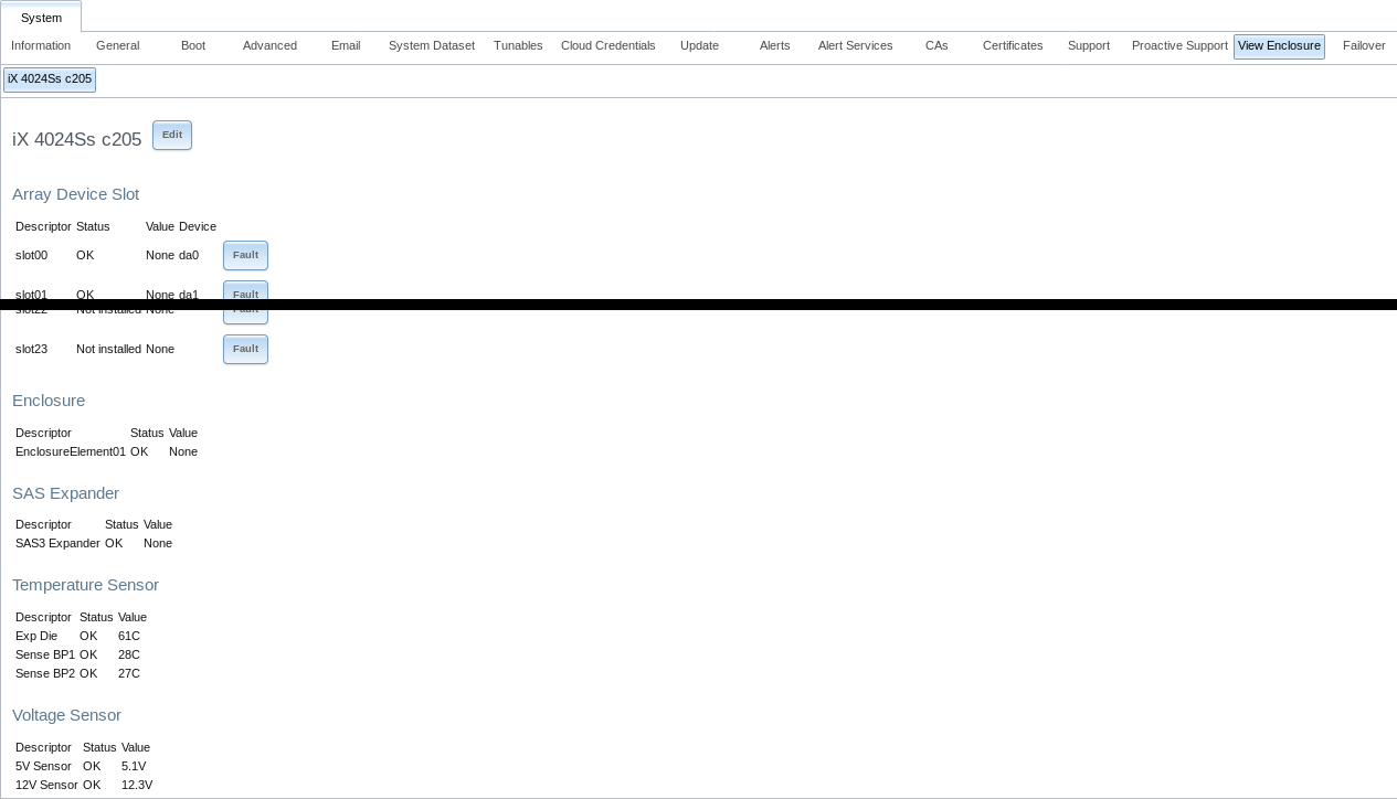
Fig. 4.16.1 View Enclosure
The screen is divided into these sections:
Array Device Slot: has an entry for each slot in the storage array, indicating the current disk status and FreeBSD device name. To blink the status light for that disk as a visual indicator, click the Identify button.
Cooling: has an entry for each fan with status and RPM.
Enclosure: shows the status of the enclosure.
Power Supply: shows the status of each power supply.
SAS Expander: shows the status of the expander.
Temperature Sensor: shows the current temperature of each expander and the disk chassis.
Voltage Sensor: shows the current voltage for each sensor, VCCP, and VCC.
4.17. Failover
If the TrueNAS® array has been licensed for High Availability (HA), a Failover tab is added to System.
TrueNAS® uses an active/standby configuration of dual storage controllers for HA. Dual-ported disk drives are connected to both storage controllers simultaneously. One storage controller is active, the other standby. The active controller sends periodic announcements to the network. If a fault occurs and the active controller stops sending the announcements, the standby controller detects this and initiates a failover. Storage and cache devices are imported on the standby controller, then I/O operations switch over to it. The standby controller then becomes the active controller. This failover operation can happen in seconds rather than the minutes of other configurations, significantly reducing the chance of a client timeout.
The Common Address Redundancy Protocol (CARP) is used to provide high availability and failover. CARP was originally developed by the OpenBSD project and provides an open source, non patent-encumbered alternative to the VRRP and HSRP protocols.
Warning
Seamless failover is only available with iSCSI or NFSv4. Other protocols will failover, but connections will be disrupted by the failover event.
To configure HA, turn on both units in the array. Use the instructions in the Console Setup Menu to log into the graphical interface for one of the units (it does not matter which one). If this is the first login, the Upload License screen is automatically displayed. Otherwise, click .
Paste the HA license received from iXsystems and press OK to activate it. The license contains the serial numbers for both units in the chassis. After the license is activated, the Failover tab is added to System and some fields are modified in Network so that the peer IP address, peer hostname, and virtual IP can be configured. An extra IPMI (Node A/B) tab will also be added so that IPMI can be configured for the other unit.
Note
The modified fields refer to this node as This Node and the other node as either A or B. The node value is hard-coded into each unit and the value that appears is automatically generated. For example, on node A, the fields refer to node B, and vice versa.
To configure HA networking, go to . The Hostname field is replaced by three fields:
- Hostname (Node A/B): enter the hostname to use for the other node.
- Hostname (This Node): enter the hostname to use for this node.
- Hostname (Virtual): Enter the fully qualified hostname plus the domain name. When using a virtualhost, this is also used as the Kerberos principal name.
Next, go to . The HA license adds several fields to the usual Interfaces screen:
- IPv4 Address (Node A/B): if the other node will use a static IP address, rather than DHCP, set it here.
- IPv4 Address (This Node): if this node will use a static IP address, rather than DHCP, set it here.
- Virtual IP: enter the IP address to use for administrative access to the array.
- Virtual Host ID: use a unique Virtual Host ID (VHID) on the broadcast segment of the network. Configuring multiple Virtual IP addresses requires a separate VHID for each address.
- Critical for Failover: enable this option if a failover should occur when this interface becomes unavailable. How many seconds it takes for that failover to occur depends upon the value of the Timeout, as described in Table 4.17.1. This option is interface-specific, allowing different settings for a management network and a data network. Note that enabling this option requires the Virtual IP to be set and that at least one interface needs to be set as Critical for Failover to configure failover.
- Group: this drop-down menu is grayed out unless the Critical for Failover option is enabled. This option allows grouping multiple, critical-for-failover interfaces. Groups apply to single systems. A failover occurs when every interface in the group fails. Groups with a single interface trigger a failover when that interface fails. Configuring the system to failover when any interface fails requires marking each interface as critical and placing them in separate groups.
After the network configuration is complete, log out and log back in, this time using the Virtual IP address. Volumes and shares can now be configured as usual and configuration automatically synchronizes between the active and the standby node.
The passive or standby node indicates the virtual IP address that is used for configuration management. The standby node also has a red Standby icon and no longer accepts logins as all configuration changes must occur on the active node.
Note
After the Virtual IP address is configured, all subsequent logins should use that address.
After HA has been configured, an HA Enabled icon appears to the right of the Alert icon on the active node.
When HA has been disabled by the system administrator, the status icon changes to HA Disabled. If the standby node is not available because it is powered off, still starting up, disconnected from the network, or if failover has not been configured, the status icon changes to HA Unavailable.
The icon is red when HA is starting up, disabled, or has encountered a problem. When HA is functioning normally, the icon turns green.
The options available in are shown in Figure 4.17.1: and described in Table 4.17.1.
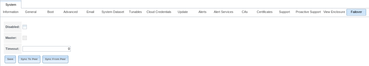
Fig. 4.17.1 Example Failover Screen
| Setting | Value | Description |
|---|---|---|
| Disabled | checkbox | Set to disable failover. The HA Enabled icon changes to HA Disabled and activates the Master field. An error message is generated if the standby node is not responding or failover is not configured. |
| Master | checkbox | Grayed out unless Disabled is selected. In that case, this option is automatically enabled on the master system, allowing the master to automatically take over when the Disabled option is deselected. |
| Timeout | integer | Specify, in seconds, how quickly failover occurs after a network failure. The default of 0 indicates that failover either occurs immediately or, if the system is using a link aggregation, after 2 seconds. |
| Sync to Peer | button | Open a dialog window to force the TrueNAS® configuration to sync from the active node to the standby node. After the sync, the standby node must be rebooted (enabled by default) to load the new configuration. Do not use this unless requested by an iXsystems support engineer, the HA daemon normally handles configuration sync automatically. |
| Sync From Peer | button | Open a dialog window to force the TrueNAS® configuration to sync from the standby node to the active node. Do not use this unless requested by an iXsystems support engineer, the HA daemon normally handles configuration sync automatically. |
Notes about High Availability and failovers:
Booting an HA pair with failover disabled causes both nodes to come up in standby mode. The web interface shows an additional Force Takeover button which can be used to force that node to take control.
Failover is not allowed if both storage controllers have the same CARP state. A critical Alert is generated and the HA icon shows HA Unavailable.
The TrueNAS® version of the ifconfig command adds two
additional fields to the output to help with failover troubleshooting:
CriticalGroupn and Interlink.
If both nodes reboot simultaneously, the GELI passphrase for an encrypted volume must be entered at the web interface login screen.
If there are a different number of disks connected to each node, an Alert is generated and the HA icon switches to HA Unavailable.