How to fix Asrock c2750d4i with C2000 bug

Ericloewe

Server Wrangler
Moderator
Joined
Feb 15, 2014
Messages
20,194
Full disclosure: This whole C2000 LPC saga has me increasingly confused the deeper I look into it.

If any of these fixes are to work, what we need is to supply a high rail to be pulled down by the CPU when it wants to output logic low (or it wants to detect the boot mode on power-up) - that's not 3.3V, it'll depend on the IC, but Intel specifies 2 V for the LPC bus. So, as long as logic high is consistently decently above 2 V, all's good.

That said, I'm not following the benefit of the divider versus a straight pull-up.
 

cj0

Cadet
Joined
Mar 3, 2023
Messages
5
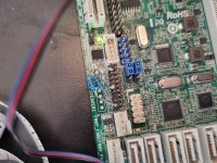
Thanks to @Ericloewe and @nogates. With an external power supply, testing leads, clips and the 10 second delay I was able to boot my no longer booting Asrock c2750d4i board (which previously showed near 97ºC CPU temperature in IPMI).

The Picotest power supply says that PCICLK consumes only 6 mA (@2.00 volts), see pictures.

A Linux reboot command restarts fine without having to do the 10 second delayed PCICLK power supply hack.

PS How hard can it be for Asrock to supply a TPMI header add-on, as a form of customer service, instead of denying warranty exchange requests. I am even willing to pay for the thing.

IMG_0330.JPG

IMG_0329.JPG
 

Ericloewe

Server Wrangler
Moderator
Joined
Feb 15, 2014
Messages
20,194
During BIOS boot, the boot process pauses until +2V signal returns.
That seems to be coherent with the observations over on the other thread, where the CPU seems to get around to booting, but then the boot process doesn't really go anywhere.
 

cj0

Cadet
Joined
Mar 3, 2023
Messages
5
Last edited:

cj0

Cadet
Joined
Mar 3, 2023
Messages
5
C2750D4I TPM-S voltage divider on a header

The 2 mm spaced 9 pin headers arrived today.

A first attempt with 470 and 470 Ohm doesn't work.
Also the clipped off terminals don't look good.
IMG_0338 470-470 Ohm leads too lang.JPG


The resistor leads were routed inside the terminal header. Thus blocking the motherboard pins that should fit in that opening:
IMG_0339 470-470 Ohm does not fit.JPG


In a second attempt the resistor leads were clipped off shorter.
The unused terminals were pulled out of the header (instead of clipped).
Bending and soldering done neater.
Also the resistor values were chosen as in the opening post: 100 ohms on the left side, and 470 ohms on the right side.
The header sits nicely on the mainboard.
And last but not least, the C2750D4I mainboard boots again.
IMG_0342 100-470 Ohm.JPG
 
Last edited:

Kortex

Dabbler
Joined
Mar 2, 2015
Messages
48
I just used the 100 + 470 ohm method and it worked. I almost can't believe it. Do I need to upgrade my firmware or disabled anything in bios for longevity's sake?
 

Ericloewe

Server Wrangler
Moderator
Joined
Feb 15, 2014
Messages
20,194
You must update the BMC's firmware to avoid an unrelated bug that destroys the BMC EEPROM.
 

Redcoat

MVP
Joined
Feb 18, 2014
Messages
2,925

XaNaX

Cadet
Joined
Apr 24, 2023
Messages
1
Another success story. Mainboard just died when running fine last week. I am remote right now and have no access to the board, bit asked a friend to make this divider connect and boot. Tested without it no vga output. With the divider works fine, boots, reboots works like a charm at least for now.
signal-2023-04-20-17-59-17-655.jpg
 

Ericloewe

Server Wrangler
Moderator
Joined
Feb 15, 2014
Messages
20,194
You'll probably want to keep those wires shorter, for better signal integrity.
 

Prong0035

Cadet
Joined
Aug 25, 2023
Messages
1
I did what the first post mentioned, using the same values, placed the same way, with short legs on the resistors and got my server back to working condition.
 

Attachments

  • ayPrlQu.jpg
    ayPrlQu.jpg
    355.6 KB · Views: 174

rayrayrayraydog

Dabbler
Joined
Oct 1, 2023
Messages
10
Hi, I have come across a very cheap C2750D4I, revision 1.03, that was supposedly working. I cannot get it to boot up however, and I've eliminated all variables like power supply and RAM. The IPMI lights come on and I can access it, but the system does not POST or display anything over VGA. I have cleared the CMOS and tried with one stick of RAM. I have also tried the 100/470 resistor trick in the OP with no luck.

Here is what I see in the IPMI after I attempt to power on the board. I don't have an oscilloscope to get any readings from it. Any ideas?
1696807321527.png
 

Ericloewe

Server Wrangler
Moderator
Joined
Feb 15, 2014
Messages
20,194
Hmm, the screenshot does paint the picture of a dodgy power rail or two...
The IPMI lights come on and I can access it, but the system does not POST or display anything over VGA
Do the fans spin up?
I don't have an oscilloscope to get any readings from it. Any ideas?
An oscilloscope wouldn't be the starting point, but a multimeter would. The board will surely have test pads for those voltage rails somewhere (finding them is likely to not be super fun, but they might be labeled). Cross-checking the BMC's measurements should narrow things down a bit.

If it is a power delivery issue, a repair will probably be too complex for most people to be comfortable with it, but any decent repair shop might be able to take it on, assuming you can narrow it down and acquire the necessary parts.
 

rayrayrayraydog

Dabbler
Joined
Oct 1, 2023
Messages
10
Hmm, the screenshot does paint the picture of a dodgy power rail or two...

Do the fans spin up?

An oscilloscope wouldn't be the starting point, but a multimeter would. The board will surely have test pads for those voltage rails somewhere (finding them is likely to not be super fun, but they might be labeled). Cross-checking the BMC's measurements should narrow things down a bit.

If it is a power delivery issue, a repair will probably be too complex for most people to be comfortable with it, but any decent repair shop might be able to take it on, assuming you can narrow it down and acquire the necessary parts.
Yes, fans connected to motherboard headers do spin up. I will bust out the multimeter and start searching. Thanks.
 

rayrayrayraydog

Dabbler
Joined
Oct 1, 2023
Messages
10
Yes, fans connected to motherboard headers do spin up. I will bust out the multimeter and start searching. Thanks.

I have powered on the board and let it sit for bit and read the following with the meter.
PCICLK - 0.435V
3v - 3.28V

EDIT:

If I connect the 100/470 resistors from the OP and press the power button, the board will sometimes keep power cycling itself on and off every few seconds. It might do this 5 - 10 times before it stops and stays on, but it never POSTs. If I connect the power supply to the board with the resistors in place, and wait 30 seconds or so before powering on, it won't power cycle over and over but won't POST either.
 
Last edited:

Ericloewe

Server Wrangler
Moderator
Joined
Feb 15, 2014
Messages
20,194
PCICLK - 0.435V
If that's the LPC clock (should be, the board doesn't have any conventional PCI devices), then it definitely screams LPC degradation. Should be reading 2.3 V or so. So it does sound like you have two separate issues ruining your day.
 

rayrayrayraydog

Dabbler
Joined
Oct 1, 2023
Messages
10
I was reading from the TPM pins PCICLK and GND for the 0.435v. I also tried the version of the fix with dual 470 ohm resistors and had the same result. Probably about time to recycle this one. :)
 
Top