5. System
The System section of the web interface contains these entries:
- General configures general settings such as HTTPS access, the language, and the timezone
- NTP Servers adds, edits, and deletes Network Time Protocol servers
- Boot creates, renames, and deletes boot environments. It also shows the condition of the Boot Pool.
- Advanced configures advanced settings such as the serial console, swap space, and console messages
- View Enclosure: view status of disk enclosures.
- Email configures the email address to receive notifications
- System Dataset configures the location where logs and reporting graphs are stored
- Alert Services configures services used to notify the administrator about system events.
- Alert Settings lists the available Alert conditions and provides configuration of the notification frequency for each alert.
- Cloud Credentials is used to enter connection credentials for remote cloud service providers
- SSH Connections manages connecting to a remote system with SSH.
- SSH Keypairs manages all private and public SSH key pairs.
- Tunables provides a front-end for tuning in real-time and to load additional kernel modules at boot time
- Update performs upgrades and checks for system updates
- CAs: import or create internal or intermediate CAs (Certificate Authorities)
- Certificates: import existing certificates or create self-signed certificates.
- Failover: manage High Availability.
- Support: view licensing information or create a support ticket.
- Proactive Support: enable and configure automatic proactive support (Silver or Gold support coverage only).
Each of these is described in more detail in this section.
5.1. General
contains options for configuring the web interface and other basic system settings.
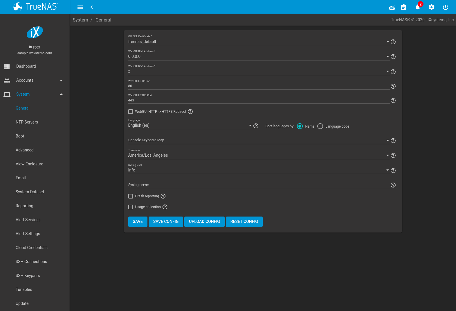
Fig. 5.1.1 General System Options
| Setting | Value | Description |
|---|---|---|
| GUI SSL Certificate | drop-down menu | The system uses a self-signed certificate to enable encrypted web interface connections. To change the default certificate, select a different created or imported certificate. |
| WebGUI IPv4 Address | drop-down menu | Choose a recent IP addresses to limit the usage when accessing the web interface. The built-in HTTP server binds to the wildcard address of 0.0.0.0 (any address) and issues an alert if the specified address becomes unavailable. |
| WebGUI IPv6 Address | drop-down menu | Choose a recent IPv6 addresses to limit the usage when accessing the web interface. The built-in HTTP server binds to the wildcard address of 0.0.0.0 (any address) and issues an alert if the specified address becomes unavailable. |
| WebGUI HTTP Port | integer | Allow configuring a non-standard port for accessing the web interface over HTTP. Changing this setting might require changing a Firefox configuration setting. |
| WebGUI HTTPS Port | integer | Allow configuring a non-standard port to access the web interface over HTTPS. |
| WebGUI HTTP -> HTTPS Redirect | checkbox | Redirect HTTP connections to HTTPS. A GUI SSL Certificate is required for HTTPS. Activating this also sets the HTTP Strict Transport Security (HSTS) maximum age to 31536000 seconds (one year). This means that after a browser connects to the TrueNAS® web interface for the first time, the browser continues to use HTTPS and renews this setting every year. |
| Language | combo box | Select a language from the drop-down menu. The list can be sorted by Name or Language code. View the translated status of a language in the webui GitHub repository. |
| Console Keyboard Map | drop-down menu | Select a keyboard layout. |
| Timezone | drop-down menu | Select a timezone. |
| Syslog level | drop-down menu | When Syslog server is defined, only logs matching this level are sent. |
| Syslog server | string | Remote syslog server DNS hostname or IP address. Nonstandard port numbers can be used by adding a colon and
the port number to the hostname, like mysyslogserver:1928. Log entries are written to local logs
and sent to the remote syslog server. |
| Crash reporting | checkbox | Send failed HTTP request data which can include client and server IP addresses, failed method call tracebacks, and middleware log file contents to iXsystems. |
| Usage Collection | checkbox | Enable sending anonymous usage statistics to iXsystems. |
After making any changes, click SAVE. Changes to any of the GUI fields can interrupt web interface connectivity while the new settings are applied.
This screen also contains these buttons:
SAVE CONFIG: save a backup copy of the current configuration database in the format hostname-version-architecture to the computer accessing the web interface. Saving the configuration after making any configuration changes is highly recommended. TrueNAS® automatically backs up the configuration database to the system dataset every morning at 3:45. However, this backup does not occur if the system is shut down at that time. If the system dataset is stored on the boot pool and the boot pool becomes unavailable, the backup will also not be available. The location of the system dataset can be viewed or set using .
Note
SSH keys are not stored in the configuration database and must be backed up separately. System host keys are files with names beginning with
ssh_host_in/usr/local/etc/ssh/. The root user keys are stored in/root/.ssh.There are two types of passwords. User account passwords for the base operating system are stored as hashed values, do not need to be encrypted to be secure, and are saved in the system configuration backup. Other passwords, like iSCSI CHAP passwords, Active Directory bind credentials, and cloud credentials are stored in an encrypted form to prevent them from being visible as plain text in the saved system configuration. The key or seed for this encryption is normally stored only on the operating system device. When Save Config is chosen, a dialog gives two options. Export Password Secret Seed includes passwords in the configuration file which allows the configuration file to be restored to a different operating system device where the decryption seed is not already present. Configuration backups containing the seed must be physically secured to prevent decryption of passwords and unauthorized access.
Warning
The Export Password Secret Seed option is off by default and should only be used when making a configuration backup that will be stored securely. After moving a configuration to new hardware, media containing a configuration backup with a decryption seed should be securely erased before reuse.
Export Pool Encryption Keys includes the encryption keys of encrypted pools in the configuration file. The encyrption keys are restored if the configuration file is uploaded to the system using UPLOAD CONFIG.
UPLOAD CONFIG: allows browsing to the location of a previously saved configuration file to restore that configuration.
RESET CONFIG: reset the configuration database to the default base version. This does not delete user SSH keys or any other data stored in a user home directory. Since configuration changes stored in the configuration database are erased, this option is useful when a mistake has been made or to return a test system to the original configuration.
5.2. NTP Servers
The network time protocol (NTP) is used to synchronize the time on the computers in a network. Accurate time is necessary for the successful operation of time sensitive applications such as Active Directory or other directory services. By default, TrueNAS® is pre-configured to use three public NTP servers. If the network is using a directory service, ensure that the TrueNAS® system and the server running the directory service have been configured to use the same NTP servers.
Available NTP servers can be found at https://support.ntp.org/bin/view/Servers/NTPPoolServers. For time accuracy, choose NTP servers that are geographically close to the physical location of the TrueNAS® system.
Click and ADD to add an NTP server. Figure 5.2.1 shows the configuration options. Table 5.2.1 summarizes the options available when adding or editing an NTP server. ntp.conf(5) explains these options in more detail.
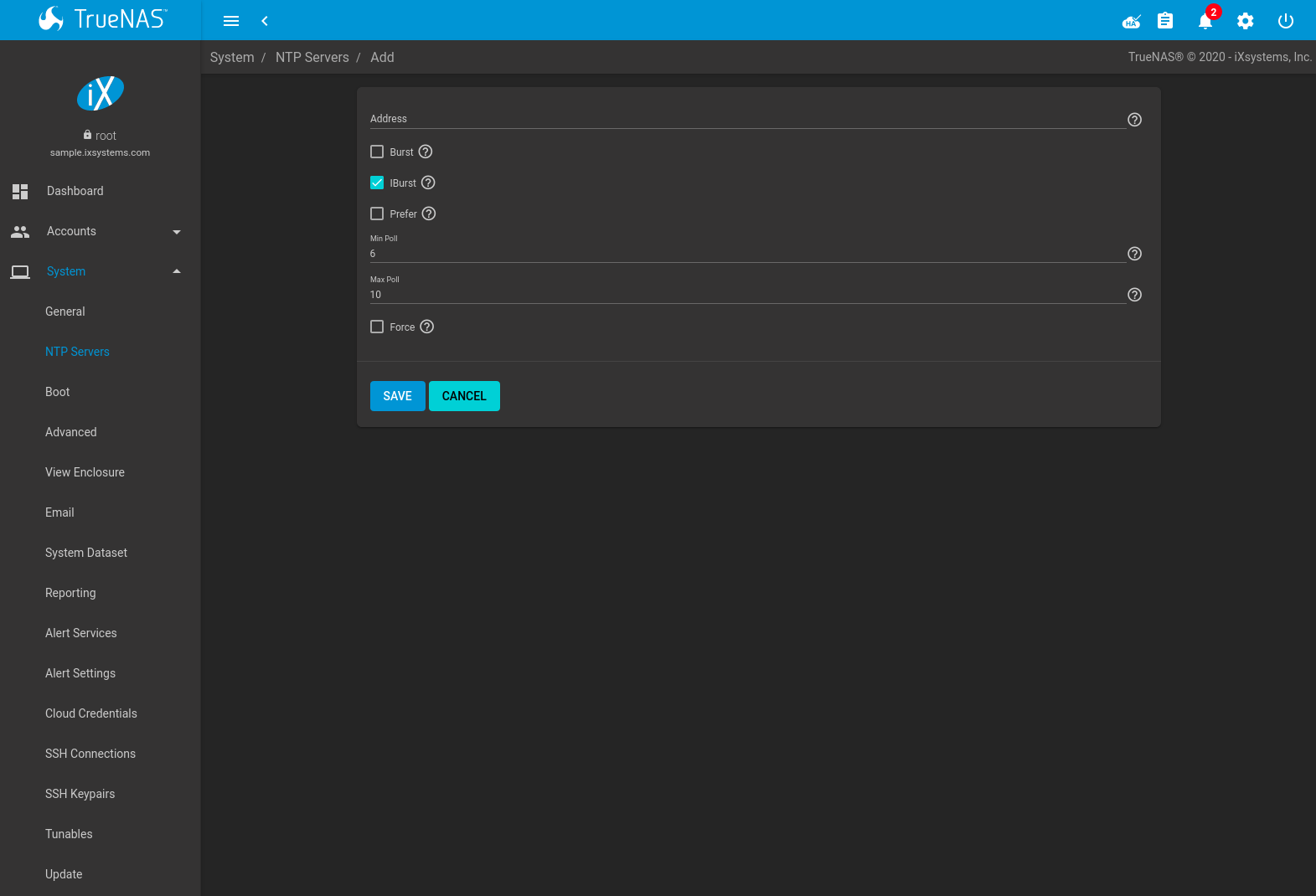
Fig. 5.2.1 Add an NTP Server
| Setting | Value | Description |
|---|---|---|
| Address | string | Enter the hostname or IP address of the NTP server. |
| Burst | checkbox | Recommended when Max. Poll is greater than 10. Only use on personal servers. Do not use with a public NTP server. |
| IBurst | checkbox | Speed up the initial synchronization, taking seconds rather than minutes. |
| Prefer | checkbox | This option is only recommended for highly accurate NTP servers, such as those with time monitoring hardware. |
| Min Poll | integer | The minimum polling interval, in seconds, as a power of 2. For example, 6 means 2^6, or 64 seconds. The default is 6, minimum value is 4. |
| Max Poll | integer | The maximum polling interval, in seconds, as a power of 2. For example, 10 means 2^10, or 1,024 seconds. The default is 10, maximum value is 17. |
| Force | checkbox | Force the addition of the NTP server, even if it is currently unreachable. |
5.3. Boot
TrueNAS® supports a ZFS feature known as multiple boot environments. With multiple boot environments, the process of updating the operating system becomes a low-risk operation. The updater automatically creates a snapshot of the current boot environment and adds it to the boot menu before applying the update.
Note
Boot environments are separate from the configuration database. Boot environments are a snapshot of the operating system at a specified time. When a TrueNAS® system boots, it loads the specified boot environment, or operating system, then reads the configuration database to load the current configuration values. If the intent is to make configuration changes rather than operating system changes, make a backup of the configuration database first using the instructions in System –> General.
The example shown in Figure 5.3.1, includes the two boot environments that are created when TrueNAS® is installed. The Initial-Install boot environment can be booted into if the system needs to be returned to a non-configured version of the installation.
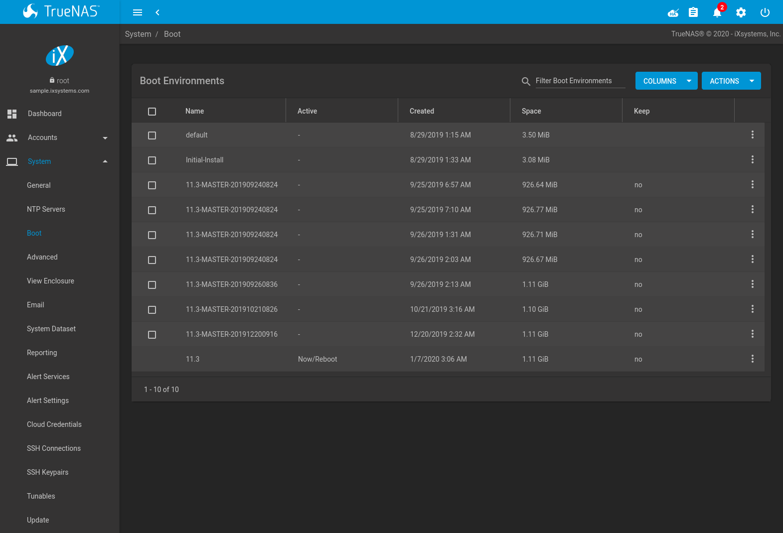
Fig. 5.3.1 Viewing Boot Environments
Each boot environment entry contains this information:
- Name: the name of the boot entry as it will appear in the boot menu. Alphanumeric characters, dashes (-), underscores (_), and periods (.) are allowed.
- Active: indicates which entry will boot by default if the user does not select another entry in the boot menu.
- Created: indicates the date and time the boot entry was created.
- Space: displays the size of the boot environment.
- Keep: indicates whether or not this boot environment can be pruned if an update does not have enough space to proceed. Click (Options) and Keep for an entry if that boot environment should not be automatically pruned.
Click (Options) on an entry to access actions specific to that entry:
- Activate: only appears on entries which are not currently set to Active. Changes the selected entry to the default boot entry on next boot. The status changes to Reboot and the current Active entry changes from Now/Reboot to Now, indicating that it was used on the last boot but will not be used on the next boot.
- Clone: makes a new boot environment from the selected boot environment. When prompted for the name of the clone, alphanumeric characters, dashes (-), underscores (_), and periods (.) are allowed.
- Rename: used to change the name of the boot environment. Alphanumeric characters, dashes (-), underscores (_), and periods (.) are allowed.
- Delete: used to delete the highlighted entry, which also removes that entry from the boot menu. Since an activated entry cannot be deleted, this button does not appear for the active boot environment. To delete an entry that is currently activated, first activate another entry. Note that this button does not appear for the default boot environment as this entry is needed to return the system to the original installation state.
- Keep: used to toggle whether or not the updater can prune (automatically delete) this boot environment if there is not enough space to proceed with the update.
Click ACTIONS to:
- Add: make a new boot environment from the active environment. The
active boot environment contains the text
Now/Rebootin the Active column. Only alphanumeric characters, underscores, and dashes are allowed in the Name. - Stats/Settings: display statistics for the operating system device: condition, total and used size, and date and time of the last scrub. By default, the operating system device is scrubbed every 7 days. To change the default, input a different number in the Automatic scrub interval (in days) field and click UPDATE INTERVAL.
- Boot Pool Status: display the status of each device in the operating system device, including any read, write, or checksum errors.
- Scrub Boot Pool: perform a manual scrub of the operating system device.
5.3.1. Operating System Device Mirroring
is used to manage the devices comprising the operating system device. An example is seen in Figure 5.3.2.
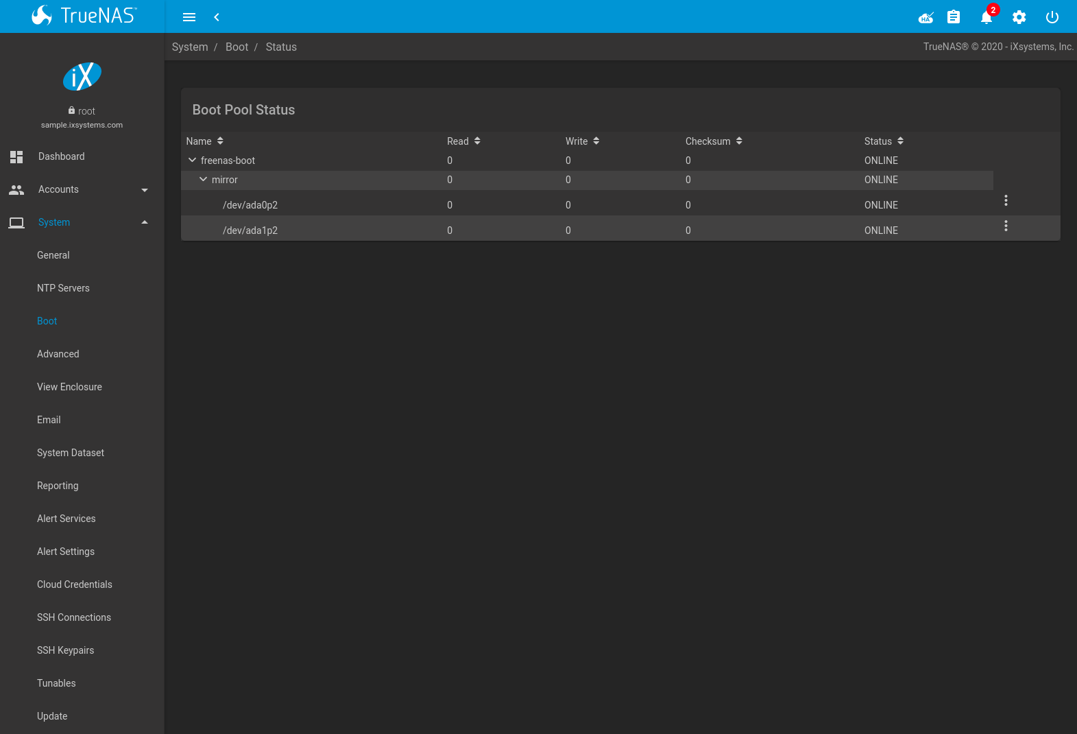
Fig. 5.3.2 Viewing the Status of the Operating System Device
TrueNAS® supports 2-device mirrors for the operating system device. In a mirrored configuration, a failed device can be detached and replaced.
Click (Options) on a device entry to access actions specific to that device:
- Attach: use to add a second device to create a mirrored operating system device. If another device is available, it appears in the Member disk drop-down menu. Select the desired device. The Use all disk space option controls the capacity made available to the operating system device. By default, the new device is partitioned to the same size as the existing device. When Use all disk space is enabled, the entire capacity of the new device is used. If the original operating system device fails and is detached, the boot mirror will consist of just the newer drive, and will grow to whatever capacity it provides. However, new devices added to this mirror must now be as large as the new capacity. Click SAVE to attach the new disk to the mirror.
- Detach: remove the failed device from the mirror so that it can be replaced.
- Replace: once the failed device has been detached, select the new replacement device from the Member disk drop-down menu to rebuild the mirror.
5.4. Advanced
is shown in Figure 5.4.1. The configurable settings are summarized in Table 5.4.1.
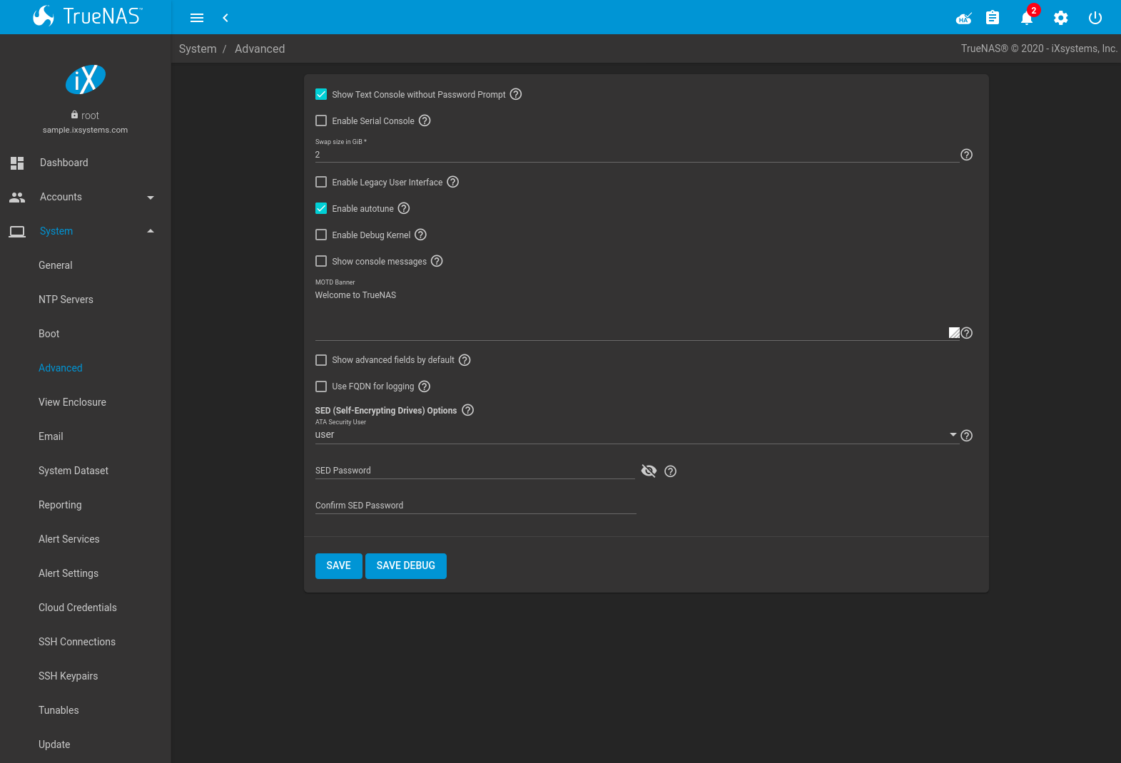
Fig. 5.4.1 Advanced Screen
| Setting | Value | Description |
|---|---|---|
| Show Text Console without Password Prompt | checkbox | Set for the text console to be available without entering a password. |
| Enable Serial Console | checkbox | Do not enable this option if the serial port is disabled. Adds the Serial Port and Serial Speed fields. |
| Serial Port | string | Select the serial port address in hex. |
| Serial Speed | drop-down menu | Select the speed in bps used by the serial port. |
| Enable Legacy User Interface | checkbox | WARNING: The legacy user interface is deprecated. All management should be performed through the new user interface. Shows legacy UI login buttons on the web interface log in screen and Settings menu. These buttons allow switching to the interface that was available with TrueNAS® 11.2 and earlier. |
| Enable autotune | checkbox | Enable the Autotune script which attempts to optimize the system based on the installed hardware. Warning: Autotuning is only used as a temporary measure and is not a permanent fix for system hardware issues. |
| Enable Debug Kernel | checkbox | Use a debug version of the kernel on the next boot. |
| Show console messages | checkbox | Display console messages from /var/log/console.log in real time at bottom of browser
window. Click the console to bring up a scrollable screen. Set the Stop refresh
option in the scrollable screen to pause updates. Unset to continue watching messages as they
occur. When this option is set, a button to show the console log appears on busy spinner dialogs. |
| MOTD banner | string | This message is shown when a user logs in with SSH. |
| Show advanced fields by default | checkbox | Show Advanced Mode fields by default. |
| Use FQDN for logging | checkbox | Include the Fully-Qualified Domain Name (FQDN) in logs to precisely identify systems with similar hostnames. |
| ATA Security User | drop-down menu | User passed to camcontrol security -u for unlocking SEDs. Values are User or Master. |
| SED Password | string | Global password used to unlock Self-Encrypting Drives. |
| Reset SED Password | checkbox | Select to clear the Password for SED column of . |
Click the SAVE button after making any changes.
This tab also contains this button:
SAVE DEBUG: used to generate text files that contain diagnostic information. After the debug data is collected, the system prompts for a location to save the compressed .tgz file.
5.4.1. Autotune
TrueNAS® provides an autotune script which optimizes the system. The Enable autotune option in is enabled by default, so this script runs automatically. Leaving autotune enabled is recommended unless advised otherwise by an iXsystems support engineer.
If the autotune script adjusts any settings, the changed values appear in . While these values can be modified and overridden, speak to a support engineer first. Manual changes can have a negative impact on system performance. Note that deleting tunables that were created by autotune only affects the current session, as autotune-set tunables are recreated at boot.
For those who wish to see which checks are performed, the autotune
script is located in /usr/local/bin/autotune.
5.4.2. Self-Encrypting Drives
TrueNAS® version 11.1-U5 introduced Self-Encrypting Drive (SED) support.
These SED specifications are supported:
Legacy interface for older ATA devices. Not recommended for security-critical environments
TCG Opal 1 legacy specification
TCG OPAL 2 standard for newer consumer-grade devices
TCG Opalite is a reduced form of OPAL 2
TCG Pyrite Version 1 and Version 2 are similar to Opalite, but hardware encryption is removed. Pyrite provides a logical equivalent of the legacy ATA security for non-ATA devices. Only the drive firmware is used to protect the device.
Danger
Pyrite Version 1 SEDs do not have PSID support and can become unusable if the password is lost.
TCG Enterprise is designed for systems with many data disks. These SEDs do not have the functionality to be unlocked before the operating system boots.
See this Trusted Computing Group® and NVM Express® joint white paper for more details about these specifications.
TrueNAS® implements the security capabilities of camcontrol for legacy devices and sedutil-cli for TCG devices. When managing a SED from the command line, it is recommended to use the sedhelper wrapper script for sedutil-cli to ease SED administration and unlock the full capabilities of the device. Examples of using these commands to identify and deploy SEDs are provided below.
A SED can be configured before or after assigning the device to a pool.
By default, SEDs are not locked until the administrator takes ownership of them. Ownership is taken by explicitly configuring a global or per-device password in the TrueNAS® web interface and adding the password to the SEDs. Adding SED passwords to TrueNAS® also allows TrueNAS® to automatically unlock SEDs.
A password-protected SED protects the data stored on the device when the device is physically removed from the TrueNAS® system. This allows secure disposal of the device without having to first wipe the contents. Repurposing a SED on another system requires the SED password.
5.4.2.1. Deploying SEDs
Run sedutil-cli --scan in the Shell to detect and list devices. The second column of the results identifies the drive type:
- no indicates a non-SED device
- 1 indicates a legacy TCG OPAL 1 device
- 2 indicates a modern TCG OPAL 2 device
- L indicates a TCG Opalite device
- p indicates a TCG Pyrite 1 device
- P indicates a TCG Pyrite 2 device
- E indicates a TCG Enterprise device
Example:
root@truenas1:~ # sedutil-cli --scan
Scanning for Opal compliant disks
/dev/ada0  No  32GB SATA Flash Drive SFDK003L
/dev/ada1  No  32GB SATA Flash Drive SFDK003L
/dev/da0   No  HGST    HUS726020AL4210  A7J0
/dev/da1   No  HGST    HUS726020AL4210  A7J0
/dev/da10    E WDC     WUSTR1519ASS201  B925
/dev/da11    E WDC     WUSTR1519ASS201  B925
TrueNAS® supports setting a global password for all detected SEDs or setting individual passwords for each SED. Using a global password for all SEDs is strongly recommended to simplify deployment and avoid maintaining separate passwords for each SED.
5.4.2.1.1. Setting a global password for SEDs
Go to and enter the password. Record this password and store it in a safe place!
Now the SEDs must be configured with this password. Go to the
Shell and enter sedhelper setup password, where
password is the global password entered in
.
sedhelper ensures that all detected SEDs are properly configured to use the provided password:
root@truenas1:~ # sedhelper setup abcd1234
da9                  [OK]
da10                 [OK]
da11                 [OK]
Rerun sedhelper setup password every time a new SED is placed
in the system to apply the global password to the new SED.
5.4.2.1.2. Creating separate passwords for each SED
Go to . Click (Options) for the confirmed SED, then Edit. Enter and confirm the password in the SED Password and Confirm SED Password fields.
The screen shows which disks have a configured SED password. The SED Password column shows a mark when the disk has a password. Disks that are not a SED or are unlocked using the global password are not marked in this column.
The SED must be configured to use the new password. Go to the
Shell and enter sedhelper setup --disk da1 password,
where da1 is the SED to configure and password is the created
password from
.
This process must be repeated for each SED and any SEDs added to the system in the future.
Danger
Remember SED passwords! If the SED password is lost, SEDs cannot be unlocked and their data is unavailable. Always record SED passwords whenever they are configured or modified and store them in a secure place!
5.4.2.2. Check SED Functionality
When SED devices are detected during system boot, TrueNAS® checks for configured global and device-specific passwords.
Unlocking SEDs allows a pool to contain a mix of SED and non-SED devices. Devices with individual passwords are unlocked with their password. Devices without a device-specific password are unlocked using the global password.
To verify SED locking is working correctly, go to the Shell.
Enter sedutil-cli --listLockingRange 0 password dev/da1,
where da1 is the SED and password is the global or individual
password for that SED. The command returns ReadLockEnabled: 1,
WriteLockEnabled: 1, and LockOnReset: 1 for drives
with locking enabled:
root@truenas1:~ # sedutil-cli --listLockingRange 0 abcd1234 /dev/da9
Band[0]:
    Name:            Global_Range
    CommonName:      Locking
    RangeStart:      0
    RangeLength:     0
    ReadLockEnabled: 1
    WriteLockEnabled:1
    ReadLocked:      0
    WriteLocked:     0
    LockOnReset:     1
5.4.2.3. Managing SED Passwords and Data
This section contains command line instructions to manage SED passwords and data. The command used is sedutil-cli(8). Most SEDs are TCG-E (Enterprise) or TCG-Opal (Opal v2.0). Commands are different for the different drive types, so the first step is identifying which type is being used.
Warning
These commands can be destructive to data and passwords. Keep backups and use the commands with caution.
Check SED version on a single drive, /dev/da0 in this example:
root@truenas:~ # sedutil-cli --isValidSED /dev/da0
/dev/da0 SED --E--- Micron_5N/A U402
All connected disks can be checked at once:
root@truenas:~ # sedutil-cli --scan
Scanning for Opal compliant disks
/dev/ada0 No 32GB SATA Flash Drive SFDK003L
/dev/ada1 No 32GB SATA Flash Drive SFDK003L
/dev/da0 E Micron_5N/A U402
/dev/da1 E Micron_5N/A U402
/dev/da12 E SEAGATE XS3840TE70014 0103
/dev/da13 E SEAGATE XS3840TE70014 0103
/dev/da14 E SEAGATE XS3840TE70014 0103
/dev/da2 E Micron_5N/A U402
/dev/da3 E Micron_5N/A U402
/dev/da4 E Micron_5N/A U402
/dev/da5 E Micron_5N/A U402
/dev/da6 E Micron_5N/A U402
/dev/da9 E Micron_5N/A U402
No more disks present ending scan
root@truenas:~ #
5.4.2.3.1. TCG-Opal Instructions
Reset the password without losing data:
sedutil-cli --revertNoErase oldpassword /dev/device
Use both of these commands to change the password without destroying data:
sedutil-cli --setSIDPassword oldpassword newpassword /dev/devicesedutil-cli --setPassword oldpassword Admin1 newpassword /dev/deviceWipe data and reset password to default MSID:
sedutil-cli --revertPer oldpassword /dev/device
Wipe data and reset password using the PSID:
sedutil-cli --yesIreallywanttoERASEALLmydatausingthePSID PSINODASHED /dev/device
where PSINODASHED is the PSID located on the pysical drive with no
dashes (-).
5.4.2.3.2. TCG-E Instructions
Use all of these commands to reset the password without losing data:
sedutil-cli --setSIDPassword oldpassword "" /dev/devicesedutil-cli --setPassword oldpassword EraseMaster "" /dev/devicesedutil-cli --setPassword oldpassword BandMaster0 "" /dev/devicesedutil-cli --setPassword oldpassword BandMaster1 "" /dev/deviceUse all of these commands to change the password without destroying data:
sedutil-cli --setSIDPassword oldpassword newpassword /dev/devicesedutil-cli --setPassword oldpassword EraseMaster newpassword /dev/devicesedutil-cli --setPassword oldpassword BandMaster0 newpassword /dev/devicesedutil-cli --setPassword oldpassword BandMaster1 newpassword /dev/deviceWipe data and reset password to default MSID:
sedutil-cli --eraseLockingRange 0 password /dev/<device>sedutil-cli --setSIDPassword oldpassword "" /dev/<device>sedutil-cli --setPassword oldpassword EraseMaster "" /dev/<device>Wipe data and reset password using the PSID:
sedutil-cli --yesIreallywanttoERASEALLmydatausingthePSID PSINODASHED /dev/device
where PSINODASHED is the PSID located on the pysical drive with no
dashes (-).
5.5. View Enclosure
Click to display the status of connected disks and hardware.
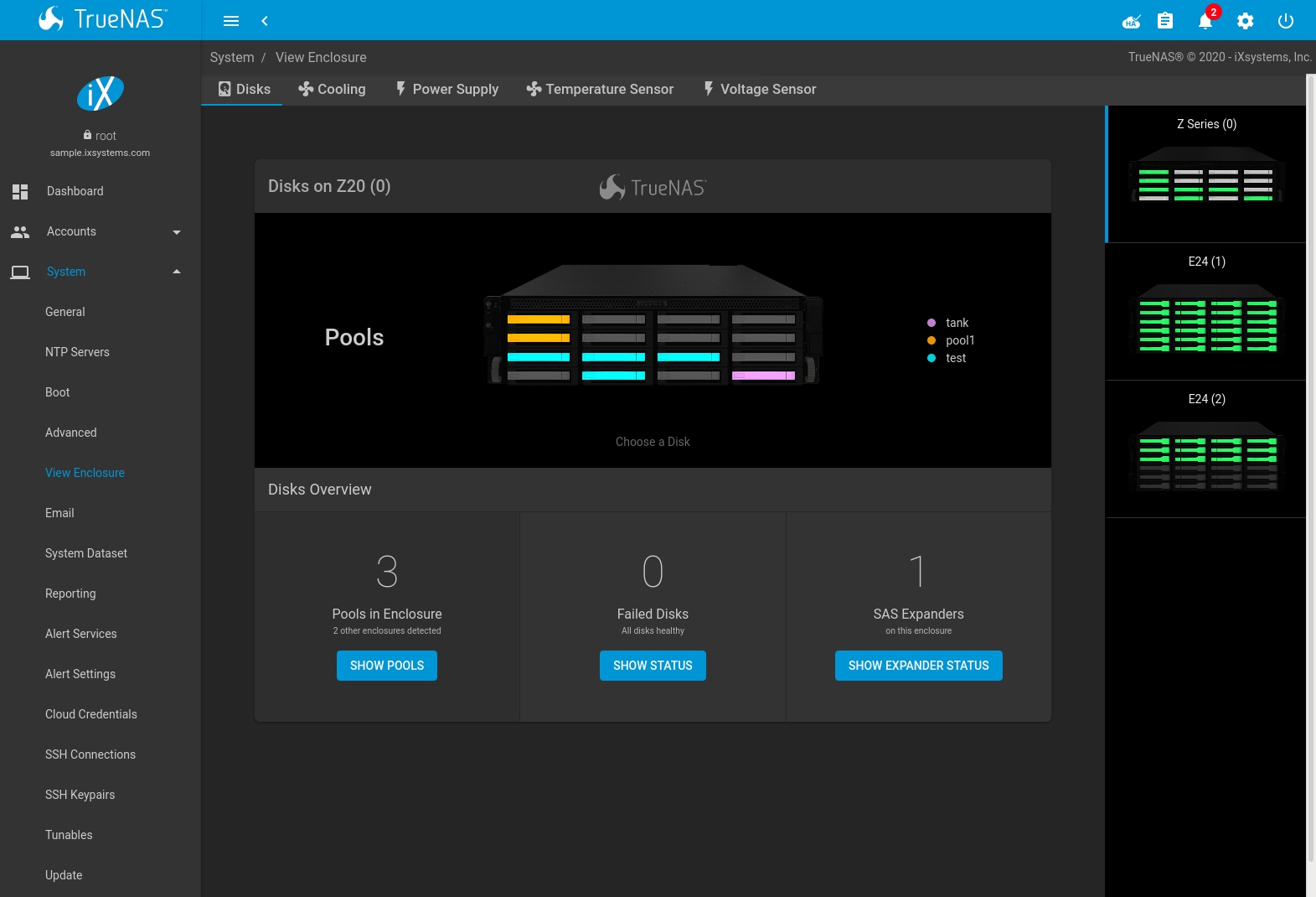
Fig. 5.5.1 View Enclosure
Detected TrueNAS® hardware is added to a column on the right side of the screen. Click an enclosure to show details about that hardware.
The screen is divided into different tabs. These tabs reflect the sensors that are active in the chosen hardware.
Disks shows a graphic representation of the TrueNAS® hardware and details about connected disks. Click any disk slot to see specific details about the disk like the FreeBSD device name, vdev assignment and function, serial number, and current drive settings. The IDENTIFY DRIVE button flashes the identification LED for the chosen drive.
The Disks Overview shows statistics about the enclosure pools, status, and detected expanders. There are options to show more details about pools in the enclosure, disk status, and expansion shelf status. Clicking any of the buttons changes the graphic to show the requested details.
Cooling has an entry for each fan with status and RPM.
Enclosure Services Controller Electronics shows the enclosure status.
Power Supply shows the status of each power supply.
SAS Connector shows the status of the expansion shelf.
Temperature Sensor shows the current temperature of each expansion shelf and the disk chassis.
Voltage Sensor shows the current voltage for each sensor, VCCP, and VCC.
5.6. Email
An automatic script sends a nightly email to the root user account containing important information such as the health of the disks. Alert events are also emailed to the root user account. Problems with Scrub Tasks are reported separately in an email sent at 03:00AM.
Note
S.M.A.R.T. reports are mailed separately to the address configured in that service.
The administrator typically does not read email directly on the TrueNAS® system. Instead, these emails are usually sent to an external email address where they can be read more conveniently. It is important to configure the system so it can send these emails to the administrator’s remote email account so they are aware of problems or status changes.
The first step is to set the remote address where email will be sent. Go to , click (Options) and Edit for the root user. In the Email field, enter the email address on the remote system where email is to be sent, like admin@example.com. Click SAVE to save the settings.
Additional configuration is performed with , shown in Figure 5.6.1.
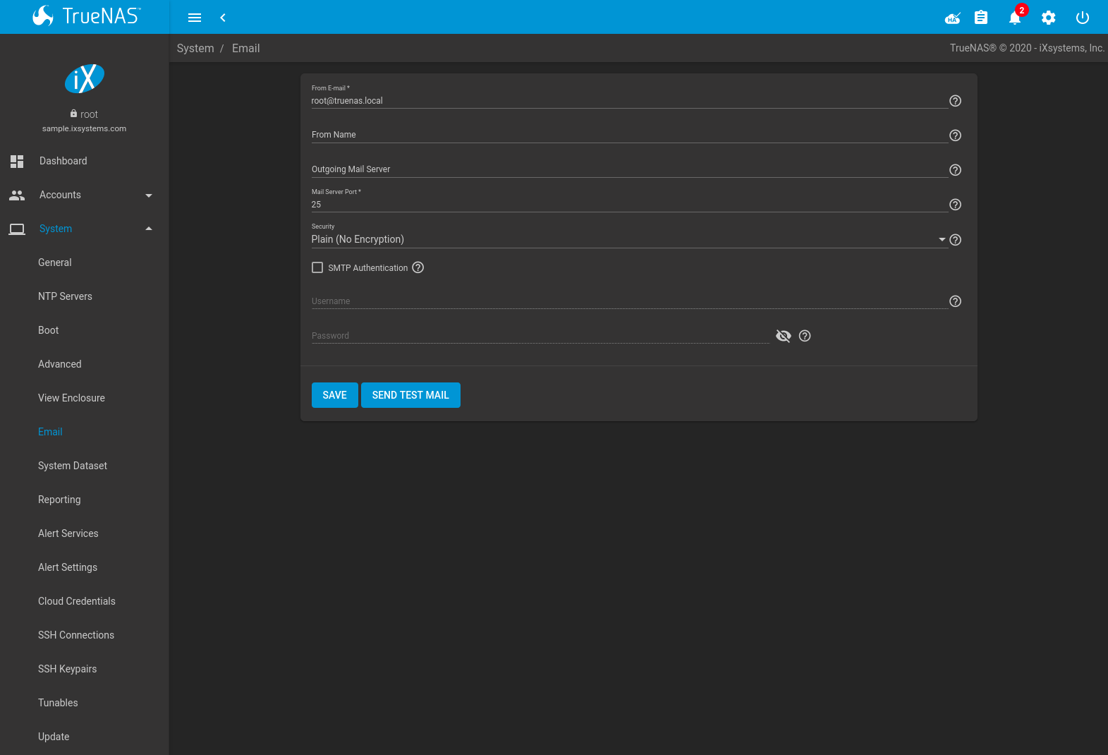
Fig. 5.6.1 Email Screen
| Setting | Value | Description |
|---|---|---|
| From E-mail | string | The envelope From address shown in the email. This can be set to make filtering mail on the receiving system easier. |
| From Name | string | The friendly name to show in front of the sending email address. |
| Outgoing Mail Server | string or IP address | Hostname or IP address of SMTP server used for sending this email. |
| Mail Server Port | integer | SMTP port number. Typically 25, 465 (secure SMTP), or 587 (submission). |
| Security | drop-down menu | Choose an encryption type. Choices are Plain (No Encryption), SSL (Implicit TLS), or TLS (STARTTLS). |
| SMTP Authentication | checkbox | Enable or disable SMTP AUTH using PLAIN SASL. Setting this enables the required Username and optional Password fields. |
| Username | string | Enter the SMTP username when the SMTP server requires authentication. |
| Password | string | Enter the SMTP account password if needed for authentication. Only plain text characters (7-bit ASCII) are allowed in passwords. UTF or composed characters are not allowed. |
Click the SEND TEST MAIL button to verify that the configured email settings are working. If the test email fails, double-check that the Email field of the root user is correctly configured by clicking the Edit button for the root account in .
Configuring email for TLS/SSL email providers is described in Are you having trouble getting FreeNAS to email you in Gmail?.
5.7. System Dataset
, shown in Figure 5.7.1, is used to select the pool which contains the persistent system dataset. The system dataset stores debugging core files, encryption keys for encrypted pools, and Samba4 metadata such as the user/group cache and share level permissions.
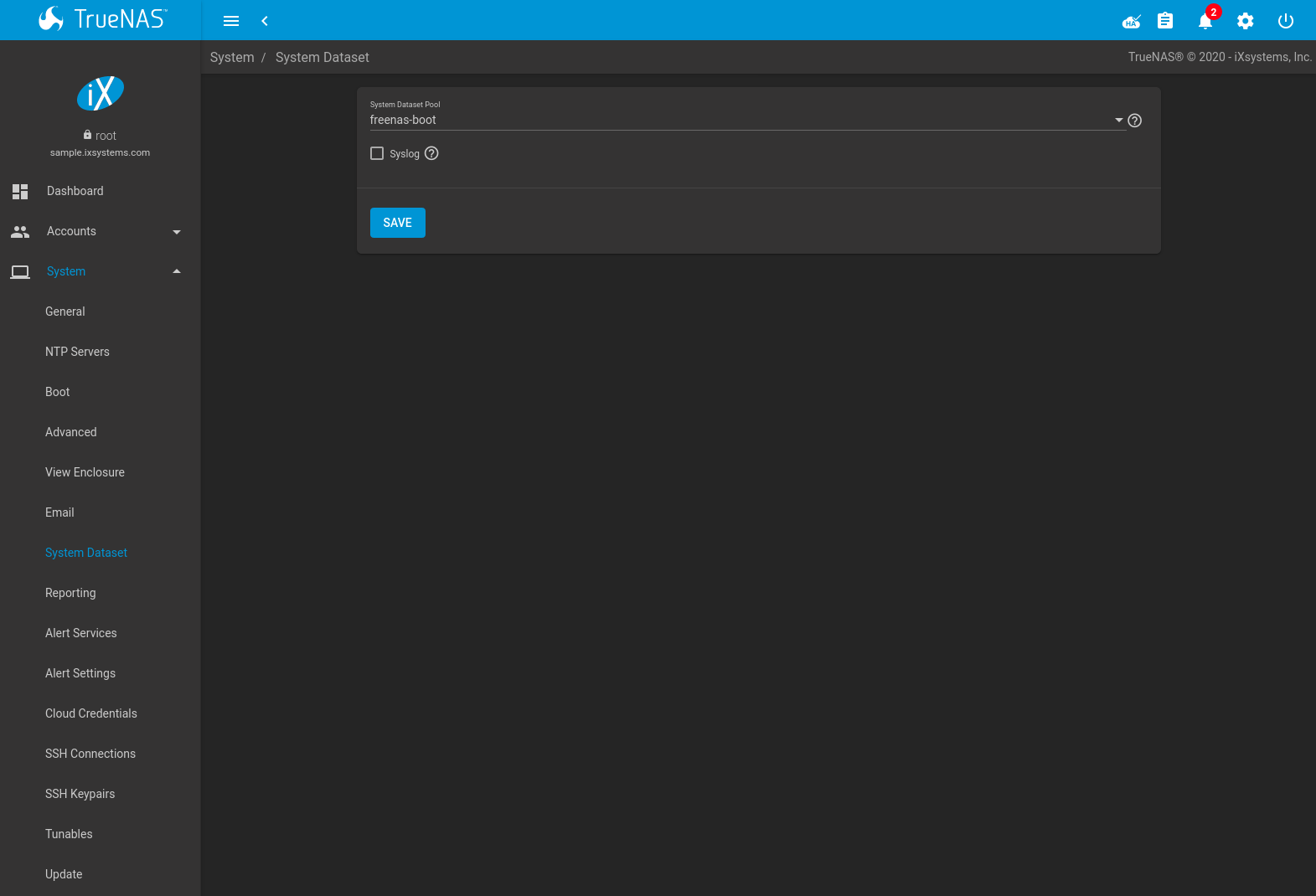
Fig. 5.7.1 System Dataset Screen
Use the System Dataset Pool drop-down menu to select the volume (pool) to contain the system dataset. The system dataset can be moved to unencrypted volumes (pools) or encrypted volumes which do not have passphrases. If the system dataset is moved to an encrypted volume, that volume is no longer allowed to be locked or have a passphrase set.
Moving the system dataset also requires rebooting the standby TrueNAS controller for High Availability TrueNAS® systems and restarting the SMB service. A dialog warns that the SMB service must be restarted, causing a temporary outage of any active SMB connections.
System logs can also be stored on the system dataset. Storing this information on the system dataset is recommended when large amounts of data is being generated and the system has limited memory or a limited capacity operating system device.
Set Syslog to store system logs on the system dataset. Leave
unset to store system logs in /var on the operating system device.
Click SAVE to save changes.
If the pool storing the system dataset is changed at a later time, TrueNAS® migrates the existing data in the system dataset to the new location.
Note
Depending on configuration, the system dataset can occupy a large amount of space and receive frequent writes. Do not put the system dataset on a flash drive or other media with limited space or write life.
5.8. Reporting
This section contains settings to customize some of the reporting tools. These settings are described in Table 5.8.1
| Setting | Value | Description |
|---|---|---|
| Report CPU usage in percent | checkbox | Report CPU usage in percent instead of units of kernel time. |
| Remote Graphite Server Hostname | string | Hostname or IP address of a remote Graphite server. |
| Graph Age in Months | integer | Maximum time a graph is stored in months (allowed values are 1 - 60). Changing this value causes the Confirm RRD Destroy dialog to appear. Changes do not take effect until the existing reporting database is destroyed. |
| Number of Graph Points | integer | Number of points for each hourly, daily, weekly, monthly, or yearly graph (allowed values are 1 - 4096). Changing this value causes the Confirm RRD Destroy checkbox to appear. Changes do not take effect until the existing reporting database is destroyed. |
Changes to Reporting settings clear the report history. To keep history with the old settings, cancel the warning dialog. Click RESET TO DEFAULTS to restore the original settings.
5.9. Alert Services
TrueNAS® can use a number of methods to notify the administrator of system events that require attention. These events are system Alerts.
Available alert services:
Warning
These alert services might use a third party commercial vendor not directly affiliated with iXsystems. Please investigate and fully understand that vendor’s pricing policies and services before using their alert service. iXsystems is not responsible for any charges incurred from the use of third party vendors with the Alert Services feature.
Select to show the Alert Services screen, Figure 5.9.1.
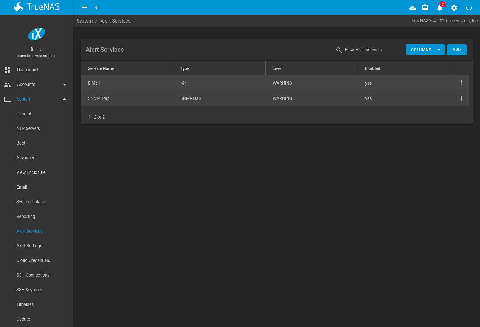
Fig. 5.9.1 Alert Services
Click ADD to display the Add Alert Service form, Figure 5.9.2.
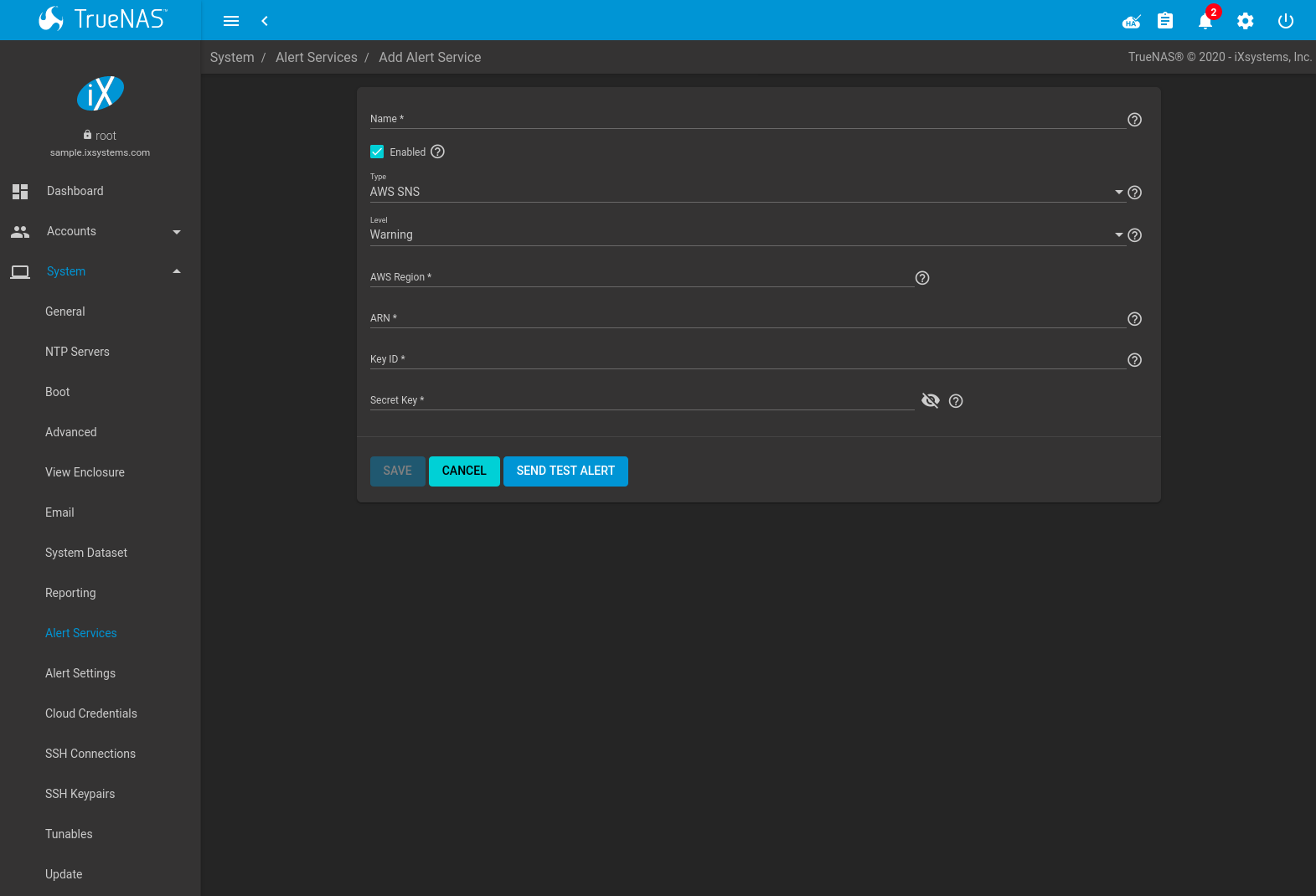
Fig. 5.9.2 Add Alert Service
Select the Type to choose an alert service to configure.
Alert services can be set for a particular severity Level. All alerts of that level are then sent out with that alert service. For example, if the E-Mail alert service Level is set to Info, any Info level alerts are sent by that service. Multiple alert services can be set to the same level. For instance, Critical alerts can be sent both by email and PagerDuty by setting both alert services to the Critical level.
The configurable fields and required information differ for each alert service. Set Enabled to activate the service. Enter any other required information and click SAVE.
Click SEND TEST ALERT to test the chosen alert service.
All saved alert services are displayed in . To delete an alert service, click (Options) and Delete. To disable an alert service temporarily, click (Options) and Edit, then unset the Enabled option.
5.10. Alert Settings
has options to configure each TrueNAS® Alert.
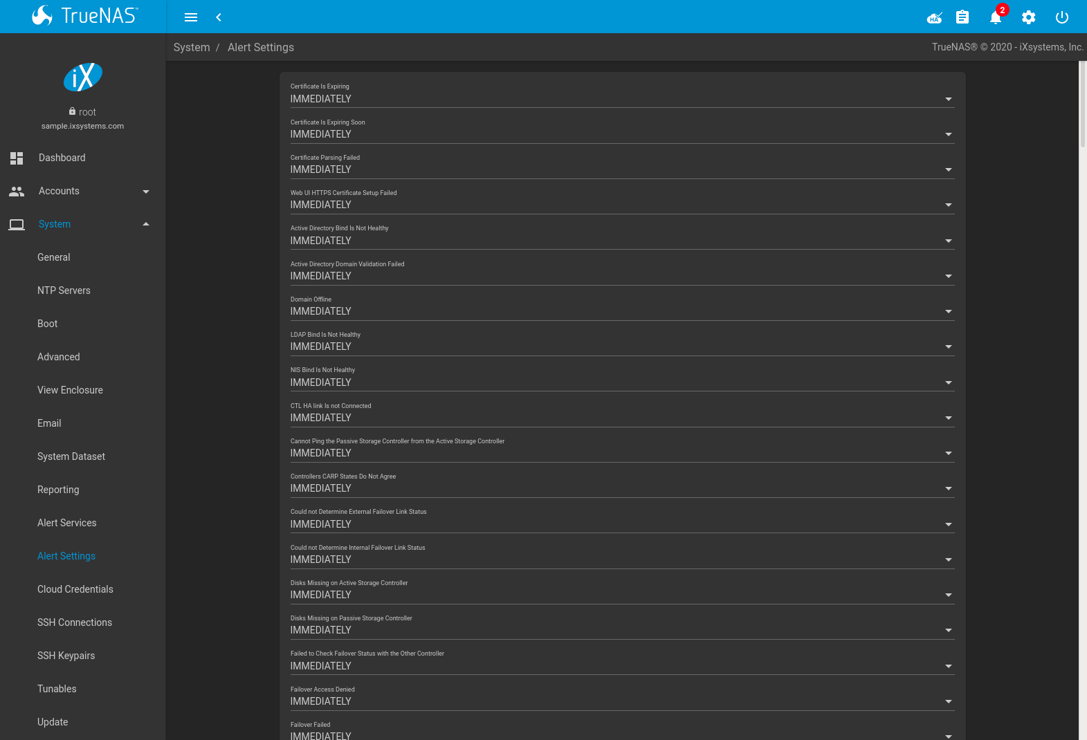
Fig. 5.10.1 Alert Settings
Alerts are grouped by web interface feature or service monitor. To adjust the alert level or notification frequency, choose an option from the drop-down menus and click SAVE.
To configure where alert notifications are sent, use Alert Services.
5.11. Cloud Credentials
TrueNAS® can use cloud services for features like Cloud Sync Tasks. The rclone credentials to provide secure connections with cloud services are entered here. Amazon S3, Backblaze B2, Box, Dropbox, FTP, Google Cloud Storage, Google Drive, HTTP, hubiC, Mega, Microsoft Azure Blob Storage, Microsoft OneDrive, pCloud, SFTP, WebDAV, and Yandex are available.
Note
The hubiC cloud service has suspended creation of new accounts.
Warning
Cloud Credentials are stored in encrypted form. To be able to restore Cloud Credentials from a saved configuration, “Export Password Secret Seed” must be set when saving that configuration.
Click to see the screen shown in Figure 5.11.1.
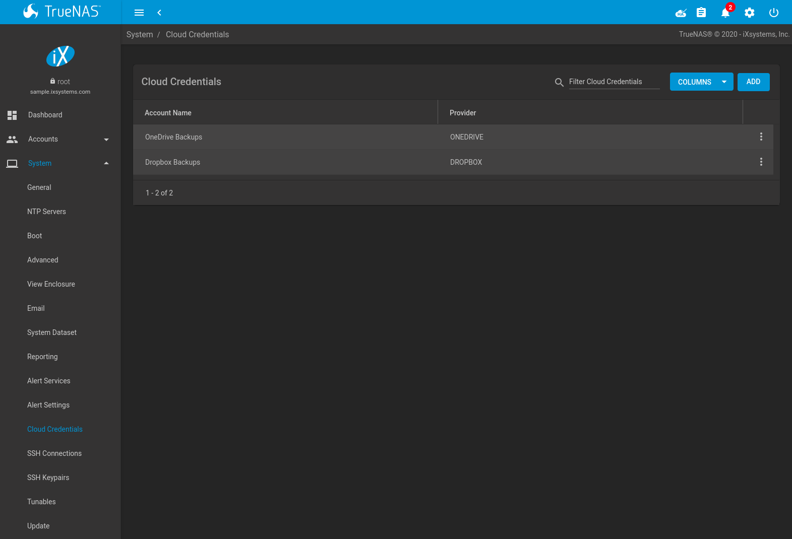
Fig. 5.11.1 Cloud Credentials List
The list shows the Account Name and Provider for each credential. There are options to Edit and Delete a credential after clicking (Options) for a credential.
Click ADD to add a new cloud credential. Choose a Provider to display any specific options for that provider. Figure 5.11.2 shows an example configuration:
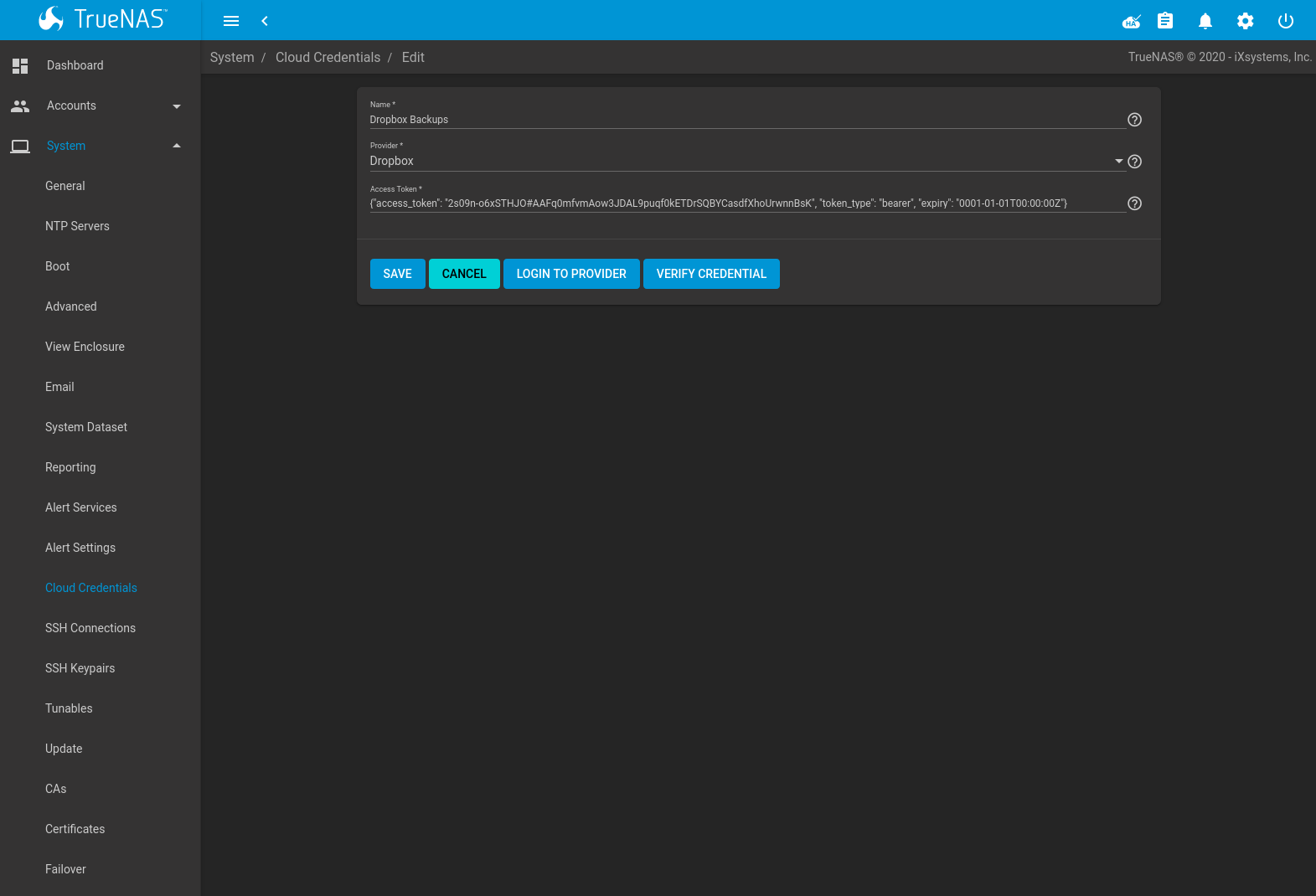
Fig. 5.11.2 Add Amazon S3 Credential
Enter a descriptive and unique name for the cloud credential in the Name field. The remaining options vary by Provider, and are shown in Table 5.11.1. Clicking a provider name opens a new browser tab to the rclone documentation for that provider.
| Provider | Setting | Description |
|---|---|---|
| Amazon S3 | Access Key ID | Enter the Amazon Web Services Key ID. This is found on Amazon AWS by going through My Account –> Security Credentials –> Access Keys. Must be alphanumeric and between 5 and 20 characters. |
| Amazon S3 | Secret Access Key | Enter the Amazon Web Services password. If the Secret Access Key cannot be found or remembered, go to My Account –> Security Credentials –> Access Keys and create a new key pair. Must be alphanumeric and between 8 and 40 characters. |
| Amazon S3 | Endpoint URL | Set Advanced Settings to access this option. S3 API endpoint URL. When using AWS, the endpoint field can be empty to use the default endpoint for the region, and available buckets are automatically fetched. Refer to the AWS Documentation for a list of Simple Storage Service Website Endpoints. |
| Amazon S3 | Region | AWS resources in a geographic area.
Leave empty to automatically detect the correct public region for the bucket. Entering a private region
name allows interacting with Amazon buckets created in that region. For example, enter
us-gov-east-1 to discover buckets created in the eastern
AWS GovCloud region. |
| Amazon S3 | Disable Endpoint Region | Set Advanced Settings to access this option. Skip automatic detection of the Endpoint URL region. Set this when configuring a custom Endpoint URL. |
| Amazon S3 | Use Signature Version 2 | Set Advanced Settings to access this option. Force using Signature Version 2 to sign API requests. Set this when configuring a custom Endpoint URL. |
| Backblaze B2 | Key ID, Application Key | Alphanumeric Backblaze B2 application keys. To
generate a new application key, log in to the Backblaze account, go to the App Keys page, and
add a new application key. Copy the keyID and applicationKey strings into the
TrueNAS® web interface fields. |
| Box | Access Token | Configured with Open Authentication. |
| Dropbox | Access Token | Configured with Open Authentication. The access token can be manually created by going to the Dropbox App Console. After creating an app, go to Settings and click Generate under the Generated access token field. |
| FTP | Host, Port | Enter the FTP host and port. |
| FTP | Username, Password | Enter the FTP username and password. |
| Google Cloud Storage | JSON Service Account Key | Upload a Google Service Account credential file. The file is created with the Google Cloud Platform Console. |
| Google Drive | Access Token, Team Drive ID | The Access Token is configured with Open Authentication. Team Drive ID is only used when connecting to a Team Drive. The ID is also the ID of the top level folder of the Team Drive. |
| HTTP | URL | Enter the HTTP host URL. |
| hubiC | Access Token | Enter the access token. See the Hubic guide for instructions to obtain an access token. |
| Mega | Username, Password | Enter the Mega username and password. |
| Microsoft Azure Blob Storage | Account Name, Account Key | Enter the Azure Blob Storage account name and key. |
| Microsoft OneDrive | Access Token, Drives List, Drive Account Type, Drive ID | The Access Token is configured with Open Authentication. Authenticating a Microsoft account adds the Drives List and selects the correct Drive Account Type. The Drives List shows all the drives and IDs registered to the Microsoft account. Selecting a drive automatically fills the Drive ID field. |
| pCloud | Access Token | Configured with Open Authentication. |
| SFTP | Host, Port, Username, Password, Private Key ID | Enter the SFTP host and port. Enter an account user name that has SSH access to the host. Enter the password for that account or import the private key from an existing SSH keypair. To create a new SSH key for this credential, open the Private Key ID drop-down and select Generate New. |
| WebDAV | URL, WebDAV service | Enter the URL and use the dropdown to select the WebDAV service. |
| WebDAV | Username, Password | Enter the username and password. |
| Yandex | Access Token | Configured with Open Authentication. |
For Amazon S3, Access Key and Secret Key values are found on the Amazon AWS website by clicking on the account name, then My Security Credentials and Access Keys (Access Key ID and Secret Access Key). Copy the Access Key value to the TrueNAS® Cloud Credential Access Key field, then enter the Secret Key value saved when the key pair was created. If the Secret Key value is unknown, a new key pair can be created on the same Amazon screen.
Open Authentication (OAuth) is used with some cloud providers. These providers have a LOGIN TO PROVIDER button that opens a dialog to log in to that provider and fill the Access Token field with valid credentials.
Enter the information and click VERIFY CREDENTIAL.
The Credential is valid. displays when the credential
information is verified.
More details about individual Provider settings are available in the rclone documentation.
5.12. SSH Connections
Secure Socket Shell (SSH) is a network protocol that provides a secure method to access and transfer files between two hosts while using an unsecure network. SSH can use user account credentials to establish secure connections, but often uses key pairs shared between host systems for authentication.
TrueNAS® uses to quickly create SSH connections and show any saved connections. These connections are required when creating a new replication to back up dataset snapshots.
The remote system must be configured to allow SSH connections. Some situations can also require allowing root account access to the remote system. For TrueNAS® systems, go to and edit the SSH service to allow SSH connections and root account access.
To add a new SSH connection, go to and click ADD.
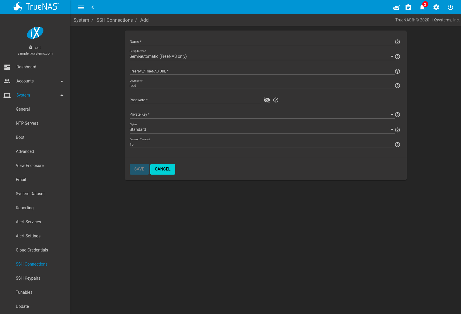
| Setting | Value | Description |
|---|---|---|
| Name | string | Descriptive name of this SSH connection. SSH connection names must be unique. |
| Setup Method | drop-down menu | How to configure the connection: Manual requires configuring authentication on the remote system. This can require copying SSH keys and modifying the root user account on that system. See Manual Setup. Semi-automatic is only functional when configuring an SSH connection between TrueNAS® systems. After authenticating the connection, all remaining connection options are automatically configured. See Semi-Automatic Setup. |
| Host | string | Enter the hostname or IP address of the remote system. Only available with Manual configurations. |
| Port | integer | Port number on the remote system to use for the SSH connection. Only available with Manual configurations. |
| FreeNAS URL | string | Hostname or IP address of the remote TrueNAS® system. Only available
with Semi-automatic configurations. A valid URL scheme is required. Example:
https://10.231.3.76 |
| Username | string | User account name to use for logging in to the remote system |
| Password | string | User account password used to log in to the TrueNAS® system. Only available with Semi-automatic configurations. |
| Private Key | drop-down menu | Choose a saved SSH Keypair or select Generate New to create a new keypair and apply it to this connection. |
| Remote Host Key | string | Remote system SSH key for this system to authenticate the connection. Only available with Manual configurations. When all other fields are properly configured, click DISCOVER REMOTE HOST KEY to query the remote system and automatically populate this field. |
| Cipher | drop-down menu | Connection security level:
|
| Connect Timeout | integer | Time (in seconds) before the system stops attempting to establish a connection with the remote system. |
Saved connections can be edited or deleted. Deleting an SSH connection also deletes or disables paired SSH Keypairs, Replication Tasks, and Cloud Credentials.
5.12.1. Manual Setup
Choosing to manually set up the SSH connection requires copying a public encryption key from the local to remote system. This allows a secure connection without a password prompt.
The examples here and in Semi-Automatic Setup refer to the TrueNAS® system that is configuring a new connection in as Host 1. The TrueNAS® system that is receiving the encryption key is Host 2.
On Host 1, go to and create a new SSH Keypair. Highlight the entire Public Key text, right-click in the highlighted area, and click Copy.
Log in to Host 2 and go to . Click (Options) for the root account, then Edit. Paste the copied key into the SSH Public Key field and click SAVE as shown in Figure 5.12.2.
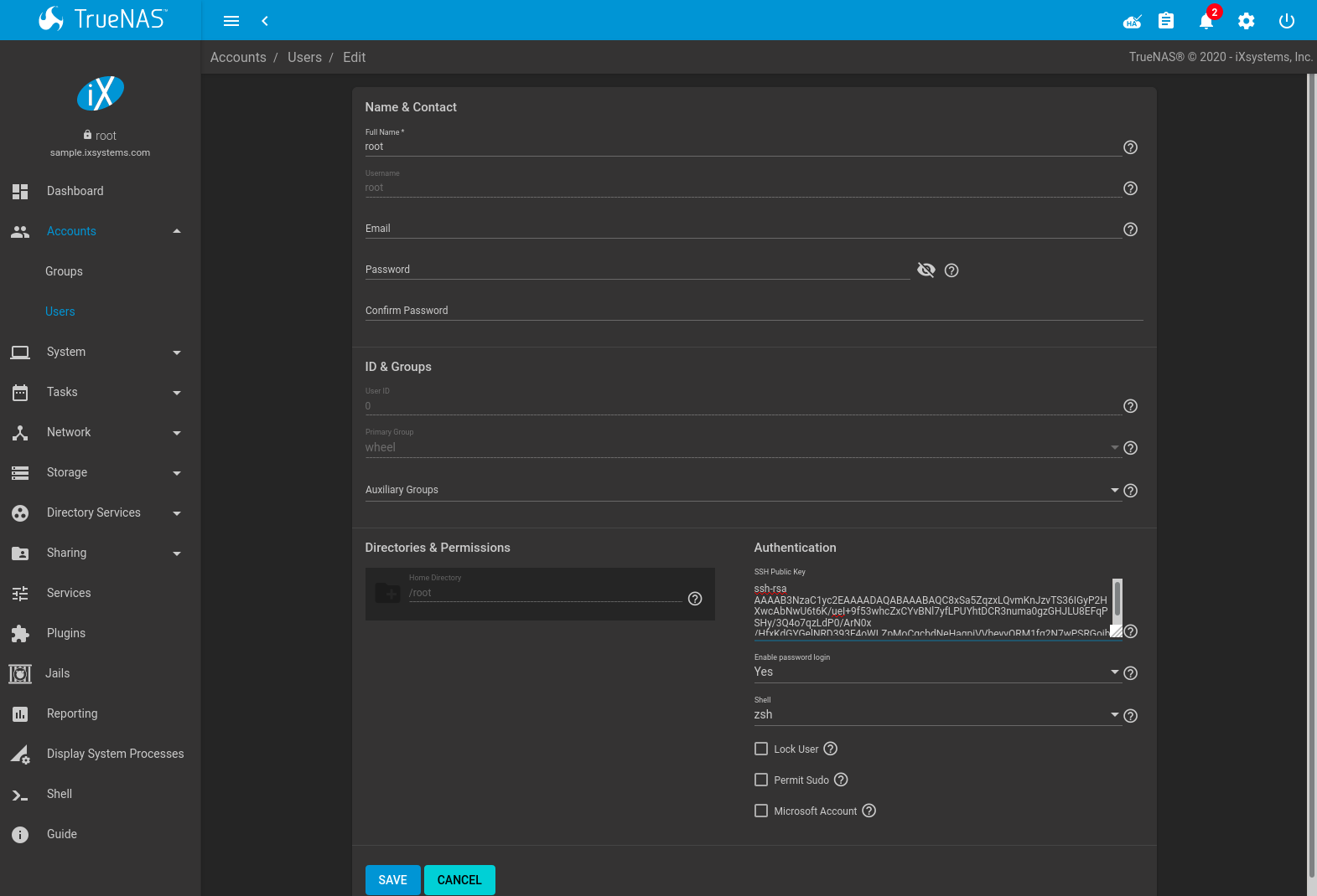
Fig. 5.12.2 Paste the Replication Key
Switch back to Host 1 and go to and click ADD. Set the Setup Method to Manual, select the previously created keypair as the Private Key, and fill in the rest of the connection details for Host 2. Click DISCOVER REMOTE HOST KEY to obtain the remote system key. Click SAVE to store this SSH connection.
5.12.2. Semi-Automatic Setup
TrueNAS® offers a semi-automatic setup mode that simplifies setting up an SSH connection with another FreeNAS or TrueNAS system. When administrator account credentials are known for Host 2, semi-automatic setup allows configuring the SSH connection without logging in to Host 2 to transfer SSH keys.
In Host 1, go to and create a new SSH Keypair. Go to and click ADD.
Choose Semi-automatic as the Setup Method. Enter the
Host 2 URL in FreeNAS URL using the format
http://freenas.remote, where freenas.remote is the
Host 2 hostname or IP address.
Enter credentials for an Host 2 user account that can accept SSH connection requests and modify Host 2. This is typically the root account.
Select the SSH keypair that was just created for the Private Key.
Fill in the remaining connection configuration fields and click SAVE. Host 1 can use this saved configuration to establish a connection to Host 2 and exchange the remaining authentication keys.
5.13. SSH Keypairs
TrueNAS® generates and stores RSA-encrypted SSH public and private keypairs in . These are generally used when configuring SSH Connections or SFTP Cloud Credentials. Encrypted keypairs or keypairs with passphrases are not supported.
To generate a new keypair, click ADD, enter a name, and click GENERATE KEYPAIR. The Private Key and Public Key fields fill with the key strings. SSH key pair names must be unique.
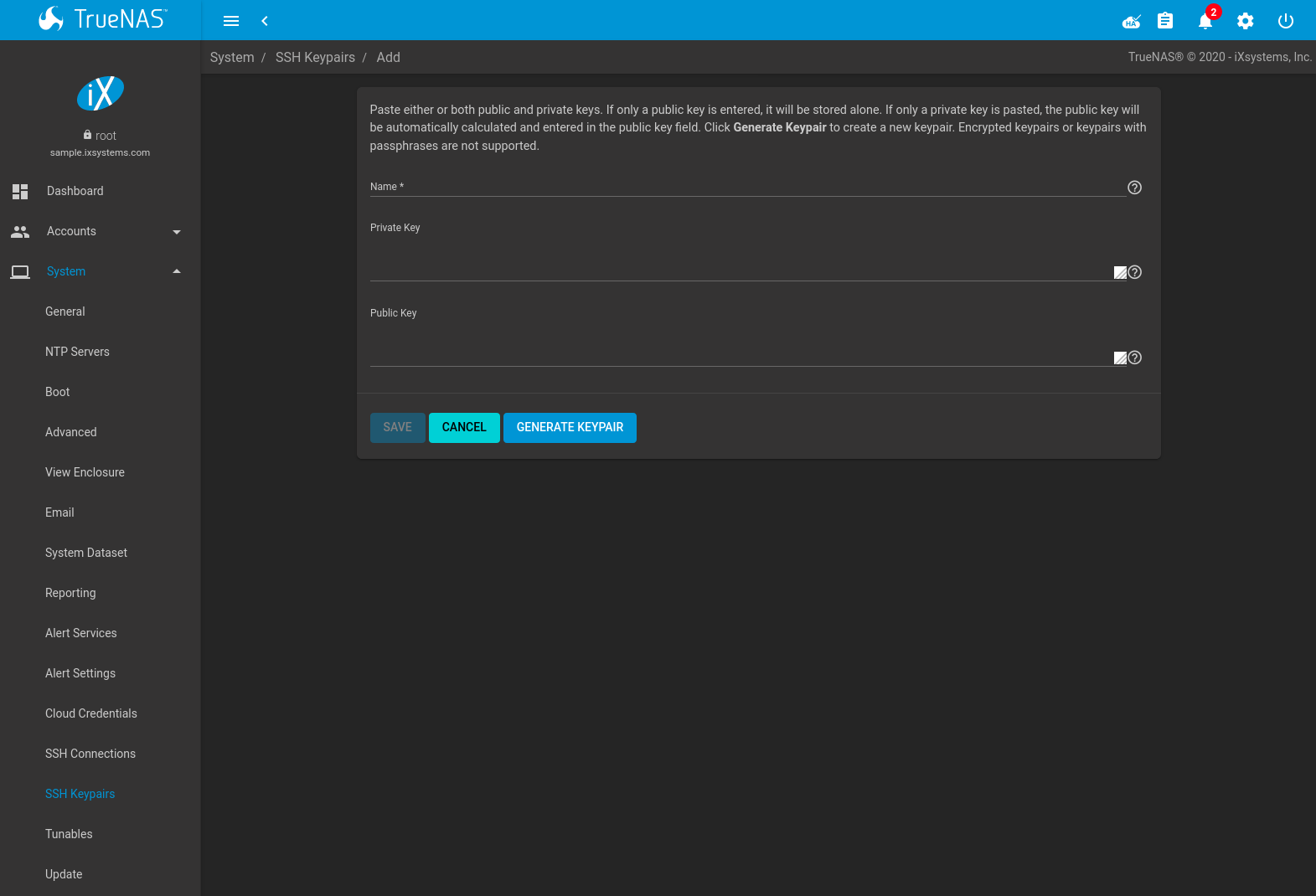
Fig. 5.13.1 Example Keypair
Click SAVE to store the new keypair. These saved keypairs can be selected later in the web interface wihout having to manually copy the key values.
Keys are viewed or modified by going to and clicking (Options) and Edit for the keypair name.
Deleting an SSH Keypair also deletes any associated SSH Connections. Replication Tasks or SFTP Cloud Credentials that use this keypair are disabled but not removed.
5.14. Tunables
can be used to manage:
- FreeBSD sysctls: a sysctl(8) makes changes to the FreeBSD kernel running on a TrueNAS® system and can be used to tune the system.
- FreeBSD loaders: a loader is only loaded when a FreeBSD-based system boots and can be used to pass a parameter to the kernel or to load an additional kernel module such as a FreeBSD hardware driver.
- FreeBSD rc.conf options:
rc.conf(5)
is used to pass system configuration options to the system startup
scripts as the system boots. Since TrueNAS® has been optimized for
storage, not all of the services mentioned in rc.conf(5) are
available for configuration. Note that in TrueNAS®, customized
rc.conf options are stored in
/tmp/rc.conf.freenas.
Warning
Adding a sysctl, loader, or rc.conf option is an
advanced feature. A sysctl immediately affects the kernel running
the TrueNAS® system and a loader could adversely affect the ability
of the TrueNAS® system to successfully boot.
Do not create a tunable on a production system before
testing the ramifications of that change.
Since sysctl, loader, and rc.conf values are specific to the kernel parameter to be tuned, the driver to be loaded, or the service to configure, descriptions and suggested values can be found in the man page for the specific driver and in many sections of the FreeBSD Handbook.
To add a loader, sysctl, or rc.conf option, go to
and click ADD to access the screen shown in
Figure 5.14.1.
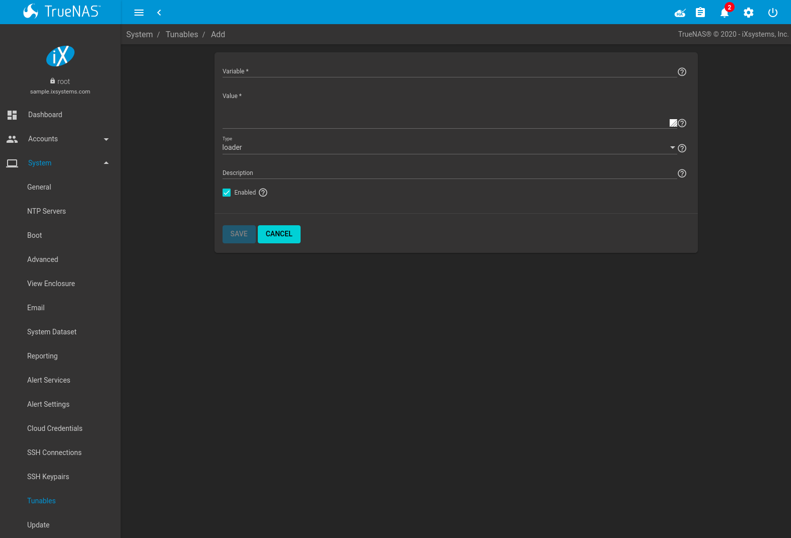
Fig. 5.14.1 Adding a Tunable
Table 5.14.1 summarizes the options when adding a tunable.
| Setting | Value | Description |
|---|---|---|
| Variable | string | The name of the sysctl or driver to load. |
| Value | integer or string | Set a value for the Variable. Refer to the man page for the specific driver or the FreeBSD Handbook for suggested values. |
| Type | drop-down menu | Choices are Loader, rc.conf, and Sysctl. |
| Description | string | Optional. Enter a description of this tunable. |
| Enabled | checkbox | Deselect this option to disable the tunable without deleting it. |
Note
As soon as a Sysctl is added or edited, the running kernel changes that variable to the value specified. However, when a Loader or rc.conf value is changed, it does not take effect until the system is rebooted. Regardless of the type of tunable, changes persist at each boot and across upgrades unless the tunable is deleted or the Enabled option is deselected.
Existing tunables are listed in . To change the value of an existing tunable, click (Options) and Edit. To remove a tunable, click (Options) and Delete.
Restarting the TrueNAS® system after making sysctl changes is recommended. Some sysctls only take effect at system startup, and restarting the system guarantees that the setting values correspond with what is being used by the running system.
The web interface does not display the sysctls that are pre-set when TrueNAS® is installed. TrueNAS® 11.3 ships with the sysctls set:
kern.metadelay=3
kern.dirdelay=4
kern.filedelay=5
kern.coredump=1
net.inet.carp.preempt=1
debug.ddb.textdump.pending=1
vfs.nfsd.tcpcachetimeo=300
vfs.nfsd.tcphighwater=150000
vfs.zfs.vdev.larger_ashift_minimal=0
net.inet.carp.senderr_demotion_factor=0
net.inet.carp.ifdown_demotion_factor=0
Do not add or edit these default sysctls as doing so may render the system unusable.
The web interface does not display the loaders that are pre-set when TrueNAS® is installed. TrueNAS® 11.3 ships with these loaders set:
autoboot_delay="2"
loader_logo="truenas-logo"
loader_menu_title="Welcome to TrueNAS"
loader_brand="truenas-brand"
loader_version=" "
kern.cam.boot_delay="10000"
debug.debugger_on_panic=1
debug.ddb.textdump.pending=1
hw.hptrr.attach_generic=0
ispfw_load="YES"
freenas_sysctl_load="YES"
hint.isp.0.topology="nport-only"
hint.isp.1.topology="nport-only"
hint.isp.2.topology="nport-only"
hint.isp.3.topology="nport-only"
module_path="/boot/kernel;/boot/modules;/usr/local/modules"
net.inet6.ip6.auto_linklocal="0"
vfs.zfs.vol.mode=2
kern.geom.label.disk_ident.enable=0
kern.geom.label.ufs.enable=0
kern.geom.label.ufsid.enable=0
kern.geom.label.reiserfs.enable=0
kern.geom.label.ntfs.enable=0
kern.geom.label.msdosfs.enable=0
kern.geom.label.ext2fs.enable=0
hint.ahciem.0.disabled="1"
hint.ahciem.1.disabled="1"
kern.msgbufsize="524288"
hw.mfi.mrsas_enable="1"
hw.usb.no_shutdown_wait=1
vfs.nfsd.fha.write=0
vfs.nfsd.fha.max_nfsds_per_fh=32
kern.ipc.nmbclusters="262144"
kern.hwpmc.nbuffers="4096"
kern.hwpmc.nsamples="4096"
hw.memtest.tests="0"
vfs.zfs.trim.enabled="0"
kern.cam.ctl.ha_mode=2
hint.ntb_hw.0.config="ntb_pmem:1:4:0,ntb_transport"
hint.ntb_transport.0.config=":3"
hw.ntb.msix_mw_idx="-1"
Do not add or edit the default tunables. Changing the default tunables can make the system unusable.
The ZFS version used in 11.3 deprecates these tunables:
kvfs.zfs.write_limit_override
vfs.zfs.write_limit_inflated
vfs.zfs.write_limit_max
vfs.zfs.write_limit_min
vfs.zfs.write_limit_shift
vfs.zfs.no_write_throttle
After upgrading from an earlier version of TrueNAS®, these tunables are automatically deleted. Please do not manually add them back.
5.15. Update
TrueNAS® has an integrated update system to make it easy to keep up to date.
5.15.1. Preparing for Updates
An update usually takes between thirty minutes and an hour. A reboot is required after the update, so it is recommended to schedule updates during a maintenance window, allowing two to three hours to update, test, and possibly roll back if issues appear. On very large systems, a proportionally longer maintenance window is recommended.
For individual support during an upgrade, please open a ticket at https://support.ixsystems.com, or call 408-943-4100 to schedule one. Scheduling at least two days in advance of a planned upgrade gives time to make sure a specialist is available for assistance.
Updates from older versions of TrueNAS® before 9.3 must be scheduled with support.
The update process will not proceed unless there is enough free space in the boot pool for the new update files. If a space warning is shown, go to Boot to remove unneeded boot environments.
Operating system updates only modify the operating system devices and do not affect end-user data on storage drives.
Available ZFS version upgrades are indicated by an Alert in the web interface. However, upgrading the ZFS version on storage drives is not recommended until after verifying that rolling back to previous versions of the operating system will not be necessary, and that interchanging the devices with some other system using an older ZFS version is not needed. After a ZFS version upgrade, the storage devices will not be accessible by older versions of TrueNAS®.
5.15.2. Updates and Trains
Cryptographically signed update files are used to update TrueNAS®. Update files provide flexibility in deciding when to upgrade the system. Go to Boot to test an update.
TrueNAS® defines software branches, known as trains. There are several trains available for updates:
For Production Use
After new bugfixes and security updates have been tested as production-ready, they are added to these trains. It is recommended to select the update train that matches the currently installed TrueNAS® feature release:
- TrueNAS-11-STABLE
- TrueNAS-11.2-STABLE
- TrueNAS-11.3-STABLE
Legacy Versions
TrueNAS-9.10-STABLE
Maintenance-only updates for the previous branch of TrueNAS®.
TrueNAS-9.3-STABLE
Maintenance-only updates for the older 9.3 branch of TrueNAS®. Use this train only at the recommendation of an iXsystems support engineer.
Warning
Only Production trains are recommended for regular usage. Other trains are made available for pre-production testing and updates to legacy versions. Pre-production testing trains are provided only to permit testing of new versions before switching to a new branch. Before using a non-production train, be prepared to experience bugs or problems. Testers are encouraged to submit bug reports at https://bug.ixsystems.com.
5.15.3. Checking for Updates
Figure 5.15.1 shows an example of the screen.
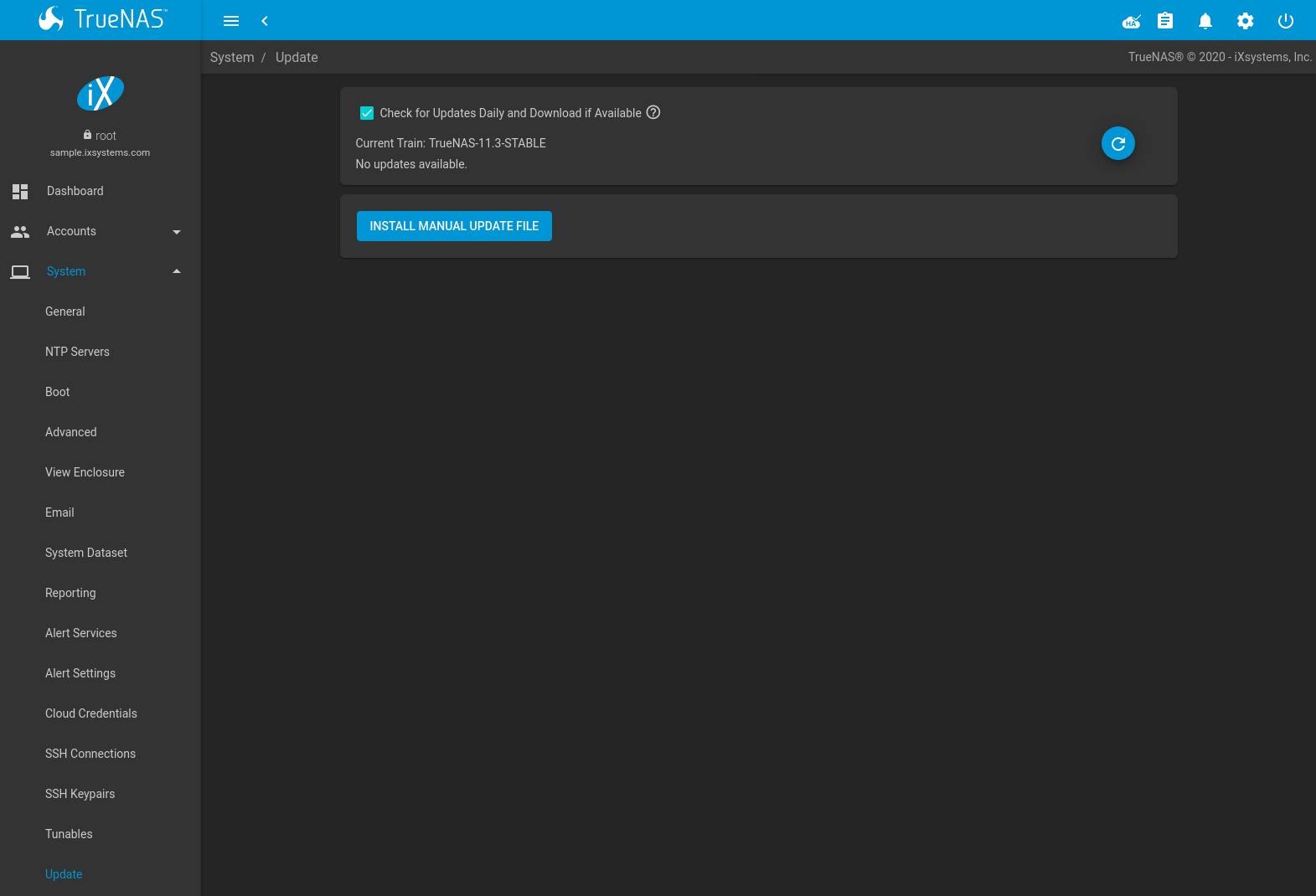
Fig. 5.15.1 Update Options
The system checks daily for updates and downloads an update if one is available. An alert is issued when a new update becomes available. The automatic check and download of updates is disabled by unsetting Check for Updates Daily and Download if Available. Click (Refresh) to perform another check for updates.
To change the train, use the drop-down menu to make a different selection.
Note
The train selector does not allow downgrades. For example, the STABLE train cannot be selected while booted into a Nightly boot environment, or a 9.10 train cannot be selected while booted into a 11 boot environment. To go back to an earlier version after testing or running a more recent version, reboot and select a boot environment for that earlier version. This screen can then be used to check for updates that train.
In the example shown in Figure 5.15.2, information about the update is displayed along with a link to the release notes. It is important to read the release notes before updating to determine if any of the changes in that release impact the use of the system.
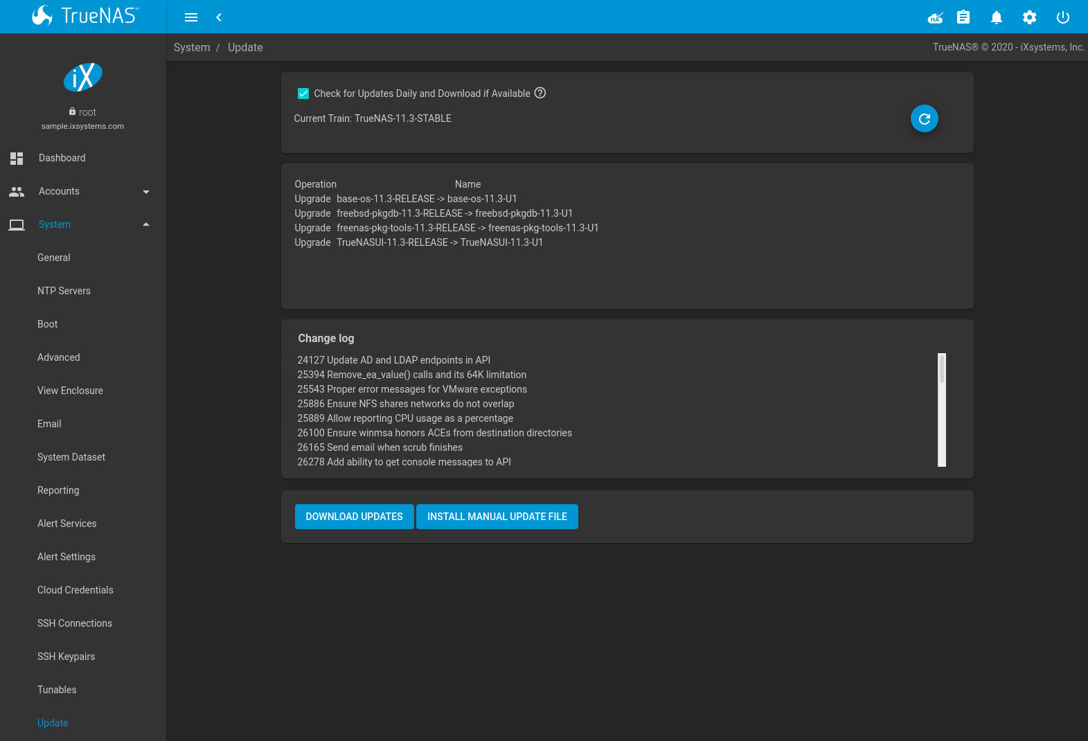
Fig. 5.15.2 Reviewing Updates
5.15.4. Saving the Configuration File
A dialog to save the system configuration file appears before installing updates.
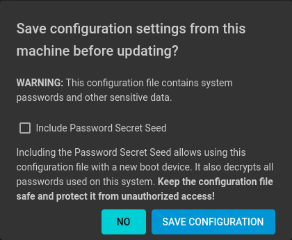
Warning
Keep the system configuration file secure after saving it. The security information in the configuration file could be used for unauthorized access to the TrueNAS® system.
5.15.5. Applying Updates
Make sure the system is in a low-usage state as described above in Preparing for Updates.
Click DOWNLOAD UPDATES to immediately download and install an update.
The Save Configuration dialog appears so the current configuration can be saved to external media.
A confirmation window appears before the update is installed. When Apply updates and reboot system after downloading is set and, clicking CONTINUE downloads, applies the updates, and then automatically reboots the system. The update can be downloaded for a later manual installation by unsetting the Apply updates and reboot system after downloading option.
APPLY PENDING UPDATE is visible when an update is downloaded and ready to install. Click the button to see a confirmation window. Setting Confirm and clicking CONTINUE installs the update and reboots the system.
Warning
Each update creates a boot environment. If the update process needs more space, it attempts to remove old boot environments. Boot environments marked with the Keep attribute as shown in Boot are not removed. If space for a new boot environment is not available, the upgrade fails. Space on the operating system device can be manually freed using . Review the boot environments and remove the Keep attribute or delete any boot environments that are no longer needed.
5.15.6. Manual Updates
Updates can also be manually downloaded and applied in .
Note
Manual updates cannot be used to upgrade from older major versions.
Go to
https://download.freenas.org/
and find an update file of the desired version. Manual update file
names end with -manual-update-unsigned.tar.
Download the file to a desktop or laptop computer. Connect to TrueNAS® with a browser and go to . Click INSTALL MANUAL UPDATE FILE.
The Save Configuration dialog opens. This makes it possible to save a copy of the current configuration to external media for backup in case of an update problem.
After the dialog closes, the manual update screen is shown:
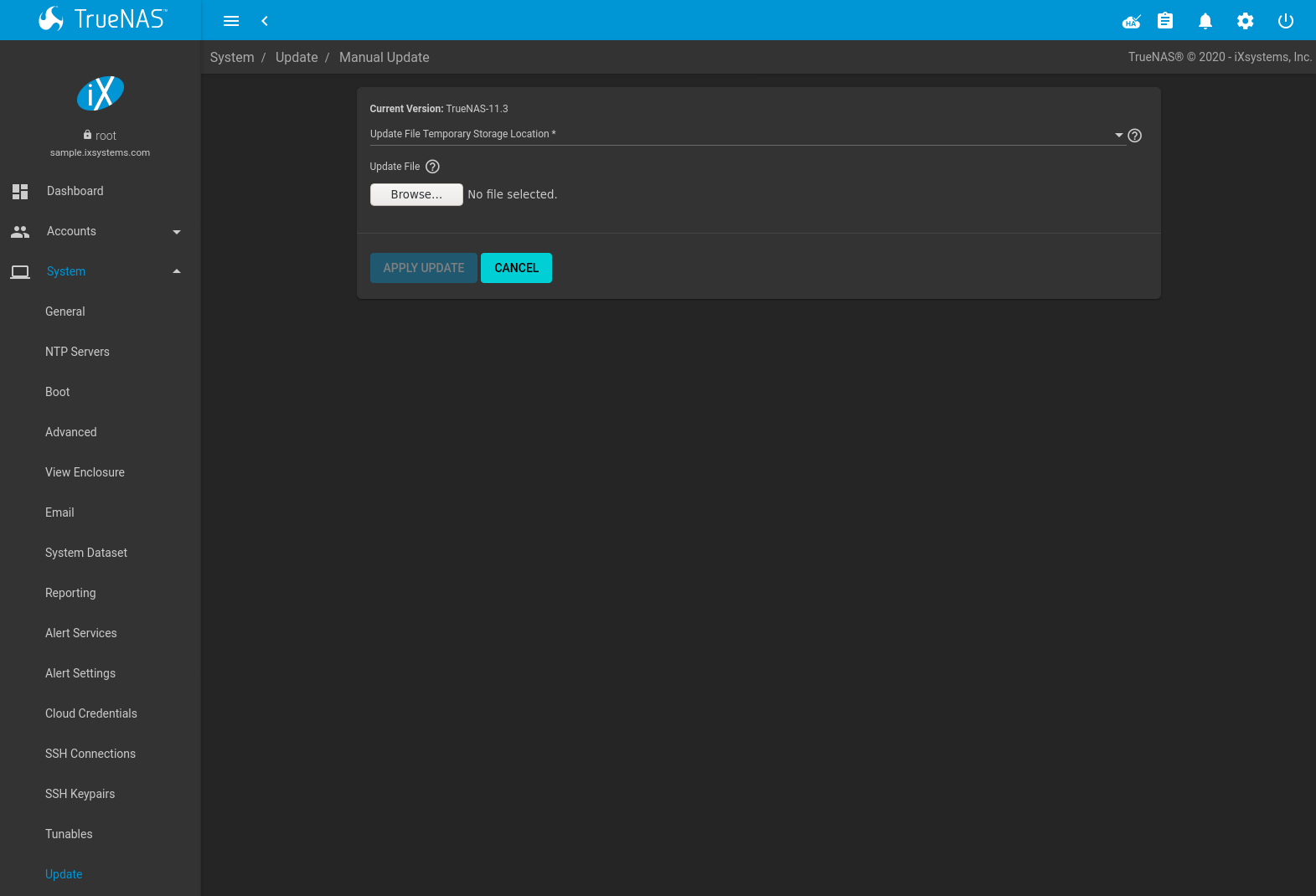
The current version of TrueNAS® is shown for verification.
Select the manual update file with the Browse button. Set Reboot After Update to reboot the system after the update has been installed. Click APPLY UPDATE to begin the update.
5.15.7. Update in Progress
Starting an update shows a progress dialog. When an update is in progress, the web interface shows an icon in the top row. Dialogs also appear in every active web interface session to warn that a system update is in progress. Do not interrupt a system update.
5.15.8. Updating from the Shell
Updates can also be performed from the Shell with an update
file. Make the update file available by copying it to the TrueNAS®
system, then run the update program, giving it the path to the file:
freenas-update update_file.
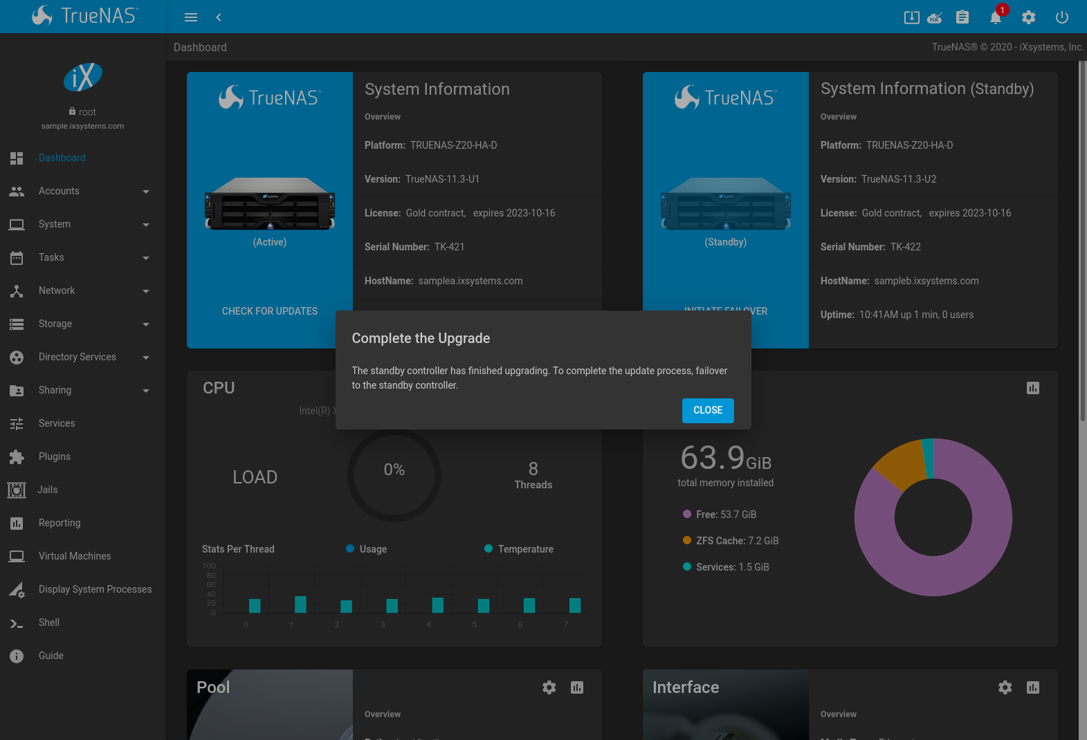
5.15.9. Updating an HA System
On the of the active TrueNAS controller, click CHECK FOR UPDATES. This button changes to UPDATES AVAILABLE when there is an available update. Clicking the button goes to . When DOWNLOAD UPDATES is clicked, it first gives an opportunity to save the current system configuration. Backing up the system configuration is strongly recommended before starting the update. Click CONTINUE to start updating both TrueNAS controllers.
A warning dialog appears for any other user that is logged into the web interface and a “System Updating” icon is shown in the top bar while the update is in progress.
Update progress is shown for both TrueNAS controllers. The standby TrueNAS controller reboots when it is finished updating. To finish updating the active TrueNAS controller, the system must fail over and deactivate the active TrueNAS controller.
To deactivate the active TrueNAS controller and finish the update, go to the and click INITIATE FAILOVER . This will temporarily interrupt TrueNAS® services and availability. To start the failover, confirm the action and click FAILOVER. The browser logs out of the web interface while the active TrueNAS controller deactivates and the other TrueNAS controller is brought online.
The browser shows the web interface login screen when the other TrueNAS controller finishes activating. Log in to the web interface and check the HA status icon in the top toolbar. This icon shows that HA is unavailable while the previously active TrueNAS controller reboots. The icon changes to show HA is available when the TrueNAS controller is back online. Click CONTINUE to finish updating the previously active TrueNAS controller and reboot it again.
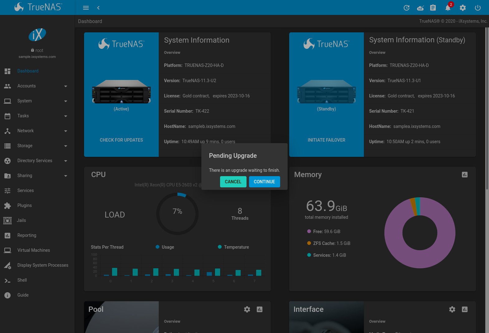
When both TrueNAS controllers are online, verify that the update is complete by going to and confirming that Version is the same on both TrueNAS controllers.
5.15.10. If Something Goes Wrong
If an update fails, an alert is issued and the details are written to
/data/update.failed.
To return to a previous version of the operating system, physical or
IPMI access to the TrueNAS® console is required. Reboot the system and
press the space bar when the boot menu appears, pausing the boot.
Select an entry with a date prior to the update, then press
Enter to boot into that version of the operating system before
the update was applied.
5.15.11. Upgrading a ZFS Pool
In TrueNAS®, ZFS pools can be upgraded from the graphical administrative interface.
Before upgrading an existing ZFS pool, be aware of these caveats first:
- the pool upgrade is a one-way street, meaning that if you change your mind you cannot go back to an earlier ZFS version or downgrade to an earlier version of the software that does not support those ZFS features.
- before performing any operation that may affect the data on a storage disk, always back up all data first and verify the integrity of the backup. While it is unlikely that the pool upgrade will affect the data, it is always better to be safe than sorry.
- upgrading a ZFS pool is optional. Do not upgrade the pool if the the possibility of reverting to an earlier version of TrueNAS® or repurposing the disks in another operating system that supports ZFS is desired. It is not necessary to upgrade the pool unless the end user has a specific need for the newer ZFS Feature Flags. If a pool is upgraded to the latest feature flags, it will not be possible to import that pool into another operating system that does not yet support those feature flags.
To perform the ZFS pool upgrade, go to and click (Settings) to upgrade. Click the Upgrade Pool button as shown in Figure 5.15.3.
Note
If the Upgrade Pool button does not appear, the pool is already at the latest feature flags and does not need to be upgraded.
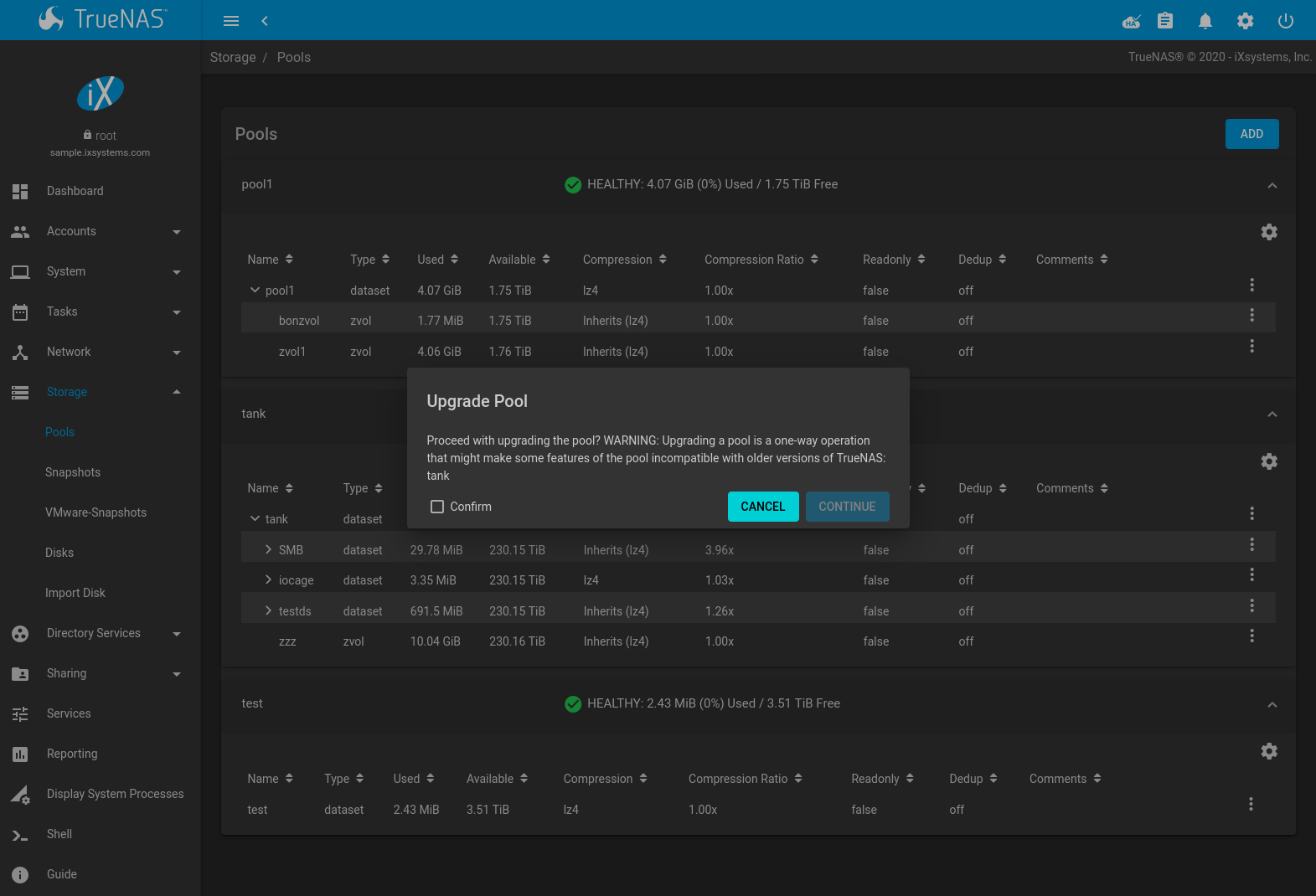
Fig. 5.15.3 Upgrading a Pool
The warning serves as a reminder that a pool upgrade is not reversible. Click OK to proceed with the upgrade.
The upgrade itself only takes a few seconds and is non-disruptive. It is not necessary to stop any sharing services to upgrade the pool. However, it is best to upgrade when the pool is not being heavily used. The upgrade process will suspend I/O for a short period, but is nearly instantaneous on a quiet pool.
5.16. CAs
TrueNAS® can act as a Certificate Authority (CA). When encrypting SSL or TLS connections to the TrueNAS® system, either import an existing certificate, or create a CA on the TrueNAS® system, then create a certificate. This certificate will appear in the drop-down menus for services that support SSL or TLS.
For secure LDAP, the public key of an existing CA can be imported with Import CA, or a new CA created on the TrueNAS® system and used on the LDAP server also.
Figure 5.16.1 shows the screen after clicking .
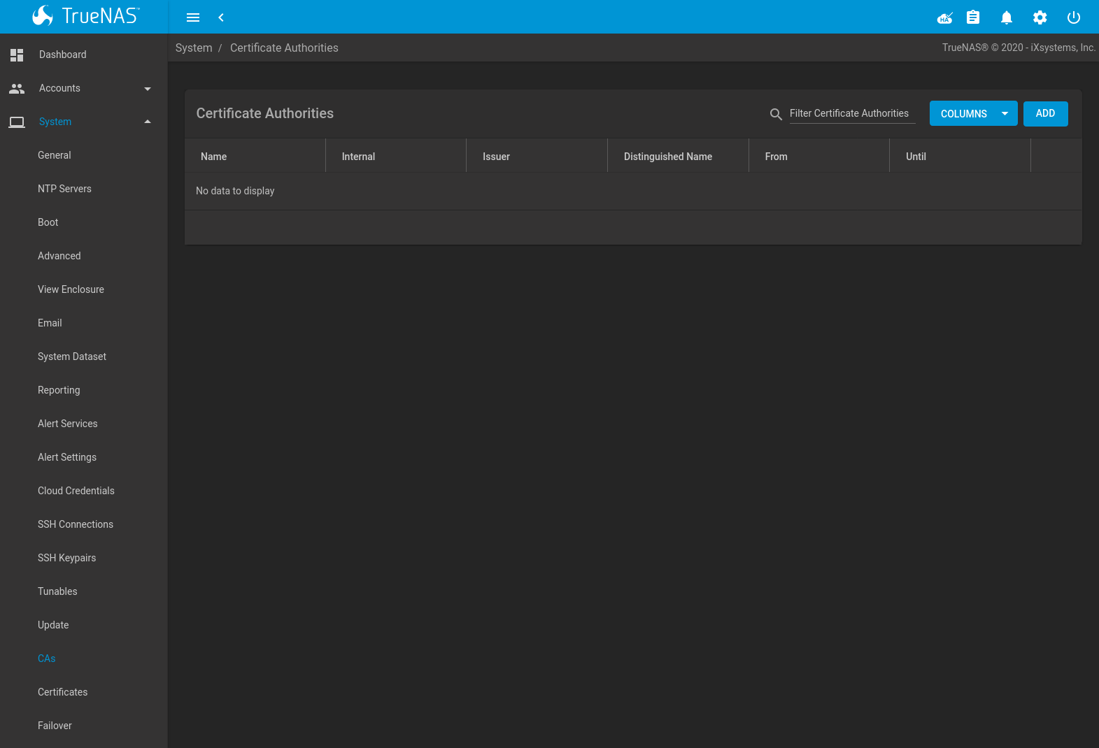
Fig. 5.16.1 Initial CA Screen
If the organization already has a CA, the CA certificate and key can be imported. Click ADD and set the Type to Import CA to see the configuration options shown in Figure 5.16.2. The configurable options are summarized in Table 5.16.1.
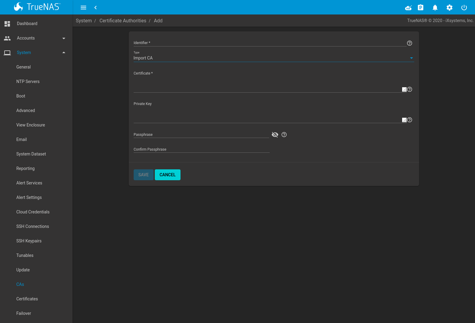
Fig. 5.16.2 Importing a CA
| Setting | Value | Description |
|---|---|---|
| Identifier | string | Enter a descriptive name for the CA using only alphanumeric,
underscore (_), and dash (-) characters. |
| Type | drop-down menu | Choose the type of CA. Choices are Internal CA, Intermediate CA, and Import CA. |
| Certificate | string | Mandatory. Paste in the certificate for the CA. |
| Private Key | string | If there is a private key associated with the Certificate, paste it here. Private keys must be at least 1024 bits long. |
| Passphrase | string | If the Private Key is protected by a passphrase, enter it here and repeat it in the “Confirm Passphrase” field. |
To create a new CA, first decide if it will be the only CA which will sign certificates for internal use or if the CA will be part of a certificate chain.
To create a CA for internal use only, click ADD and set the Type to Internal CA. Figure 5.16.3 shows the available options.
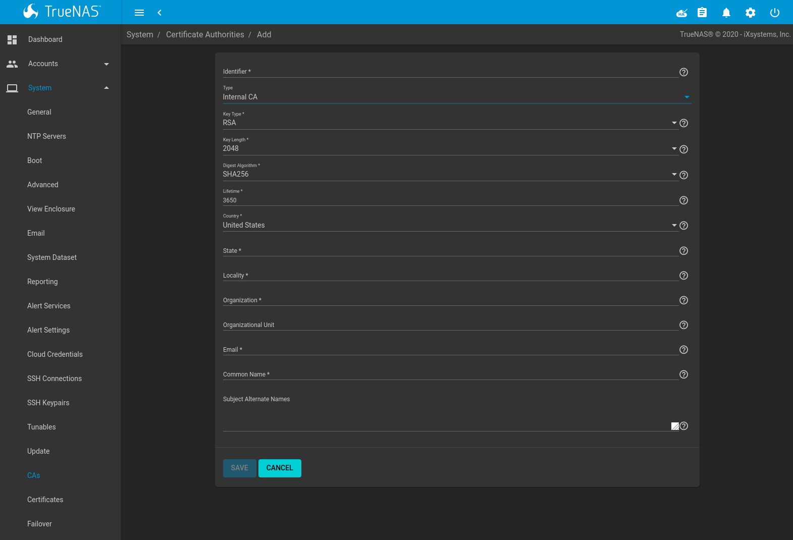
Fig. 5.16.3 Creating an Internal CA
The configurable options are described in Table 5.16.2. When completing the fields for the certificate authority, supply the information for the organization.
| Setting | Value | Description |
|---|---|---|
| Identifier | string | Enter a descriptive name for the CA using only alphanumeric,
underscore (_), and dash (-) characters. |
| Type | drop-down menu | Choose the type of CA. Choices are Internal CA, Intermediate CA, and Import CA. |
| Key Type | drop-down menu | Cryptosystem for the certificate authority key. Choose between RSA (Rivest-Shamir-Adleman) and EC (Elliptic-curve) encryption. |
| EC Curve | drop-down menu | Elliptic curve to apply to the certificate authority key. Choose from different Brainpool or SEC curve parameters. See RFC 5639 and SEC 2 for more details. Applies to EC keys only. |
| Key Length | drop-down menu | For security reasons, a minimum of 2048 is recommended. Applies to RSA keys only. |
| Digest Algorithm | drop-down menu | The default is acceptable unless the organization requires a different algorithm. |
| Lifetime | integer | The lifetime of a CA is specified in days. |
| Country | drop-down menu | Select the country for the organization. |
| State | string | Enter the state or province of the organization. |
| Locality | string | Enter the location of the organization. |
| Organization | string | Enter the name of the company or organization. |
| Organizational Unit | string | Organizational unit of the entity. |
| string | Enter the email address for the person responsible for the CA. | |
| Common Name | string | Enter the fully-qualified hostname (FQDN) of the system. The Common Name must be unique within a certificate chain. |
| Subject Alternate Names | string | Multi-domain support. Enter additional space separated domain names. |
To create an intermediate CA which is part of a certificate chain, set the Type to Intermediate CA. This screen adds one more option to the screen shown in Figure 5.16.3:
- Signing Certificate Authority: this drop-down menu is used to specify the root CA in the certificate chain. This CA must first be imported or created.
Imported or created CAs are added as entries in . The columns in this screen indicate the name of the CA, whether it is an internal CA, whether the issuer is self-signed, the CA lifetime (in days), the common name of the CA, the date and time the CA was created, and the date and time the CA expires.
Click (Options) on an existing CA to access these configuration buttons:
- View: use this option to view the contents of an existing Certificate, Private Key, or to edit the Identifier.
- Sign CSR: used to sign internal Certificate Signing Requests created using . Signing a request adds a new certificate to .
- Export Certificate: prompts to browse to the location to save a copy of the CA’s X.509 certificate on the computer being used to access the TrueNAS® system.
- Export Private Key: prompts to browse to the location to save a copy of the CA’s private key on the computer being used to access the TrueNAS® system. This option only appears if the CA has a private key.
- Delete: prompts for confirmation before deleting the CA.
5.17. Certificates
TrueNAS® can import existing certificates or certificate signing requests, create new certificates, and issue certificate signing requests so that created certificates can be signed by the CA which was previously imported or created in CAs.
Go to to add or view certificates.
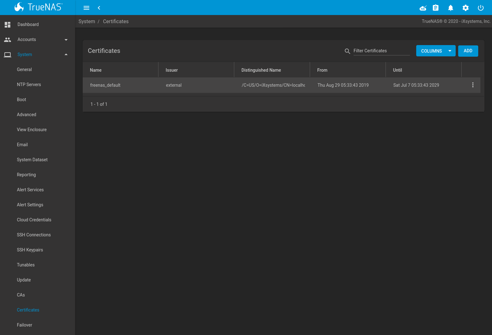
Fig. 5.17.1 Certificates
TrueNAS® uses a self-signed certificate to enable encrypted access to the web interface. This certificate is generated at boot and cannot be deleted until a different certificate is chosen as the GUI SSL Certificate.
To import an existing certificate, click ADD and set the Type to Import Certificate. Figure 5.17.2 shows the options. When importing a certificate chain, paste the primary certificate, followed by any intermediate certificates, followed by the root CA certificate.
On TrueNAS® High Availability (HA) systems, the imported certificate must include the IP addresses or DNS hostnames of both TrueNAS controllers and the CARP virtual IP address. These IP addresses or DNS hostnames can be placed in the Subject Alternative Name (SAN) x509 extension field.
The configurable options are summarized in Table 5.17.1.
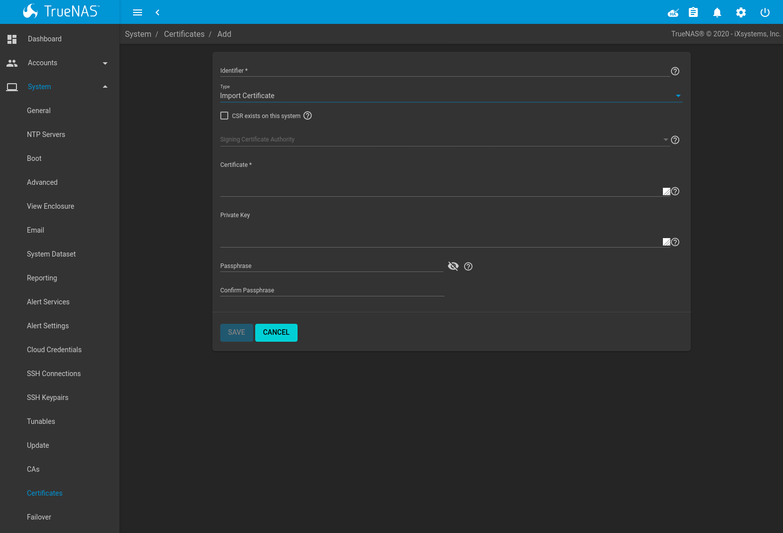
Fig. 5.17.2 Importing a Certificate
| Setting | Value | Description |
|---|---|---|
| Identifier | string | Enter a descriptive name for the certificate using only alphanumeric,
underscore (_), and dash (-) characters. |
| Type | drop-down menu | Choose the type of certificate. Choices are Internal Certificate, Certificate Signing Request, Import Certificate, and Import Certificate Signing Request. |
| CSR exists on this system | checkbox | Set when the certificate being imported already has a Certificate Signing Request (CSR) on the system. |
| Signing Certificate Authority | drop-down menu | Select a previously created or imported CA. Active when CSR exists on this system is set. |
| Certificate | string | Paste the contents of the certificate. |
| Private Key | string | Paste the private key associated with the certificate. Private keys must be at least 1024 bits long. Active when CSR exists on this system is unset. |
| Passphrase | string | If the private key is protected by a passphrase, enter it here and repeat it in the Confirm Passphrase field. Active when CSR exists on this system is unset. |
Importing a certificate signing request requires copying the contents of
the signing request and key files into the form. Having the signing
request CERTIFICATE REQUEST and PRIVATE KEY
strings visible in a separate window simplifies the import process.
| Setting | Value | Description |
|---|---|---|
| Identifier | string | Enter a descriptive name for the certificate using only alphanumeric,
underscore (_), and dash (-) characters. |
| Type | drop-down menu | Choose the type of certificate. Choices are Internal Certificate, Certificate Signing Request, Import Certificate, and Import Certificate Signing Request. |
| Signing Request | drop-down menu | Paste the CERTIFICATE REQUEST string from the signing request. |
| Private Key | string | Paste the private key associated with the certificate signing request. Private keys must be at least 1024 bits long. |
| Passphrase | string | If the private key is protected by a passphrase, enter it here and repeat it in the Confirm Passphrase field. |
To create a new self-signed certificate, set the Type to Internal Certificate to see the options shown in Figure 5.17.3. The configurable options are summarized in Table 5.17.3. When completing the fields for the certificate authority, use the information for the organization. Since this is a self-signed certificate, use the CA that was imported or created with CAs as the signing authority.
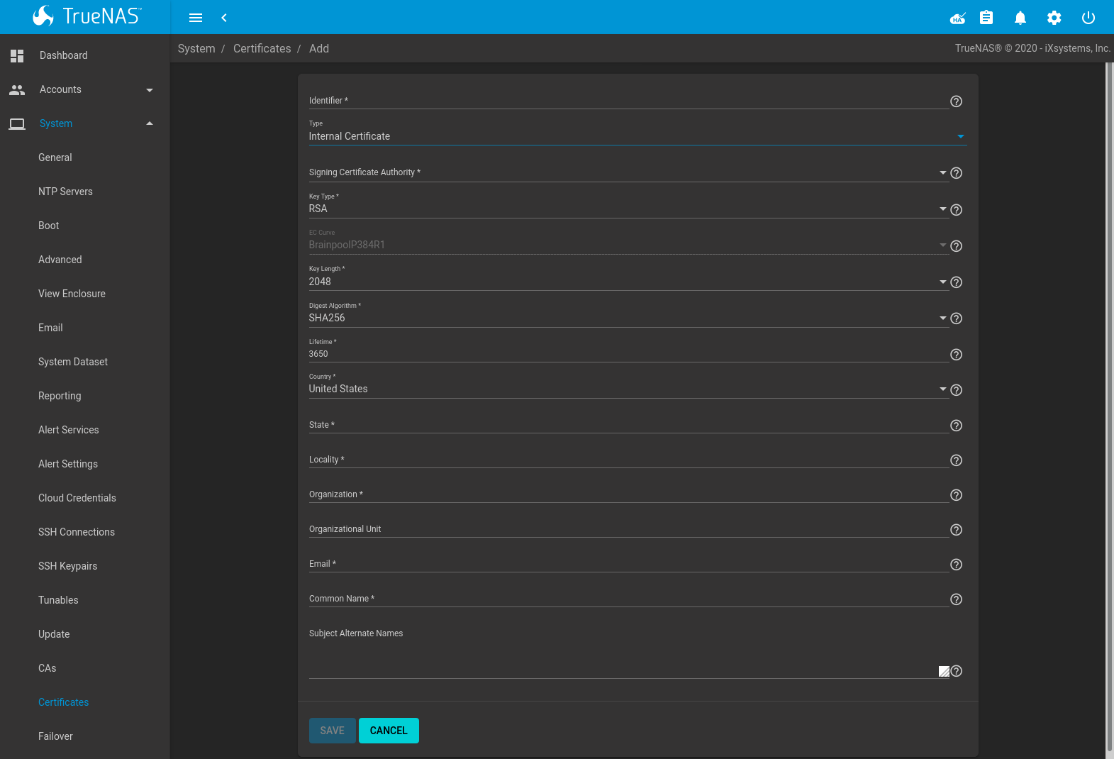
Fig. 5.17.3 Creating a New Certificate
| Setting | Value | Description |
|---|---|---|
| Identifier | string | Enter a descriptive name for the certificate using only alphanumeric,
underscore (_), and dash (-) characters. |
| Type | drop-down menu | Choose the type of certificate. Choices are Internal Certificate, Certificate Signing Request, and Import Certificate. |
| Signing Certificate Authority | drop-down menu | Select the CA which was previously imported or created using CAs. |
| Key Type | drop-down menu | Cryptosystem for the certificate key. Choose between RSA (Rivest-Shamir-Adleman) and EC (Elliptic-curve) encryption. |
| EC Curve | drop-down menu | Elliptic curve to apply to the certificate key. Choose from different Brainpool or SEC curve parameters. See RFC 5639 and SEC 2 for more details. Applies to EC keys only. |
| Key Length | drop-down menu | For security reasons, a minimum of 2048 is recommended. Applies to RSA keys only. |
| Digest Algorithm | drop-down menu | The default is acceptable unless the organization requires a different algorithm. |
| Lifetime | integer | The lifetime of the certificate is specified in days. |
| Country | drop-down menu | Select the country for the organization. |
| State | string | State or province of the organization. |
| Locality | string | Location of the organization. |
| Organization | string | Name of the company or organization. |
| Organizational Unit | string | Organizational unit of the entity. |
| string | Enter the email address for the person responsible for the CA. | |
| Common Name | string | Enter the fully-qualified hostname (FQDN) of the system. The Common Name must be unique within a certificate chain. |
| Subject Alternate Names | string | Multi-domain support. Enter additional domain names and separate them with a space. |
If the certificate is signed by an external CA, such as Verisign, instead create a certificate signing request. To do so, set the Type to Certificate Signing Request. The options from Figure 5.17.3 display, but without the Signing Certificate Authority and Lifetime fields.
Certificates that are imported, self-signed, or for which a certificate signing request is created are added as entries to . In the example shown in Figure 5.17.4, a self-signed certificate and a certificate signing request have been created for the fictional organization My Company. The self-signed certificate was issued by the internal CA named My Company and the administrator has not yet sent the certificate signing request to Verisign so that it can be signed. Once that certificate is signed and returned by the external CA, it should be imported with a new certificate set to Import Certificate. This makes the certificate available as a configurable option for encrypting connections.
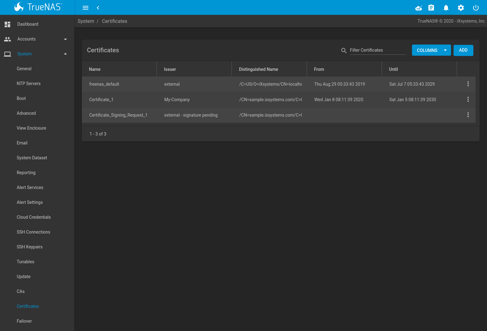
Fig. 5.17.4 Managing Certificates
Clicking (Options) for an entry shows these configuration buttons:
- View: use this option to view the contents of an existing Certificate, Private Key, or to edit the Identifier.
- Export Certificate saves a copy of the certificate or certificate signing request to the system being used to access the TrueNAS® system. For a certificate signing request, send the exported certificate to the external signing authority so that it can be signed.
- Export Private Key saves a copy of the private key associated with the certificate or certificate signing request to the system being used to access the TrueNAS® system.
- Delete is used to delete a certificate or certificate signing request.
5.18. Failover
When the TrueNAS® array has been licensed for High Availability (HA), a Failover option appears in System.
TrueNAS® uses an active/standby configuration of dual TrueNAS controllers for HA. Dual-ported disk drives are connected to both TrueNAS controllers simultaneously. One TrueNAS controller is active, the other standby. The active TrueNAS controller sends periodic announcements to the network. If a fault occurs and the active TrueNAS controller stops sending the announcements, the standby TrueNAS controller detects this and initiates a failover. Storage and cache devices are imported on the standby TrueNAS controller, then I/O operations switch over to it. The standby TrueNAS controller then becomes the active TrueNAS controller. This failover operation can happen in seconds rather than the minutes of other configurations, significantly reducing the chance of a client timeout.
Note
Seamless failover is only available with iSCSI or NFSv4. Other system services do fail over, but the connections are briefly disrupted by the event.
The Common Address Redundancy Protocol (CARP) is used to provide high availability and failover. CARP was originally developed by the OpenBSD project and provides an open source, non patent-encumbered alternative to the VRRP and HSRP protocols.
To configure HA, turn on both TrueNAS controllers. Use the IP address shown in the Console Setup Menu to access the web interface of one of the TrueNAS controllers units. Either TrueNAS controller can be used to configure HA. The Upload License dialog is shown on the first login. Otherwise, go to .
Paste the HA license received from iXsystems and press SAVE LICENSE to activate it. The license contains the serial numbers for both units in the chassis.
Activating the license adds the Failover option to System. Some fields are modified in Network so that the peer IP address, peer hostname, and virtual IP can be configured. An extra drop-down is added to IPMI to allow configuring IPMI for each TrueNAS controller. The also updates to add an entry for the standby TrueNAS controller. This entry includes a button to manually initiate a failover.
Fields modified by activating the HA license use 1, 2, or active/standby to identify the TrueNAS controllers. The numbers correspond to the TrueNAS controller labels on the TrueNAS® chassis.
To configure HA networking, go to . The Hostname field is replaced by two fields:
- Hostname: enter the hostname to use for TrueNAS Controller 1.
- Hostname (TrueNAS Controller 2): enter the hostname to use for TrueNAS controller 2.
Next, go to and click ADD. The HA license adds several fields to the Interfaces screen:
- Critical: set this option when a failover should occur if this interface becomes unavailable. How many seconds it takes for the failover to occur depends on the Timeout value, as described in Table 5.18.1. This option is interface-specific, allowing different settings for a management network and a data network. Setting this option requires the Virtual IP to be set and that at least one interface needs to be set as Critical to configure failover.
- Failover Group: allows grouping multiple, critical-for-failover interfaces. Groups apply to single systems. A failover occurs when every interface in the group fails. Groups with a single interface trigger a failover when that interface fails. Configuring the system to failover when any interface fails requires marking each interface as critical and placing them in separate groups.
- Failover VHID: use a unique Virtual Host ID (VHID) on the broadcast segment of the network. Configuring multiple Virtual IP addresses requires a separate VHID for each address.
- IP Address (This Controller): a static IP address and netmask. Required when TrueNAS controller 1 is not using DHCP.
- Failover IP Address (TrueNAS Controller 2): a static IP address and netmask. Required when TrueNAS controller 2 is not using DHCP.
- Virtual IP Address: enter the IP address to use for
administrative access to the array. The netmask
/32is reserved for this value and cannot be changed.
After the network configuration is complete, log out and log back in, this time using the virtual IP address. Pools and shares can now be configured as usual and configuration automatically synchronizes between the active and standby TrueNAS controllers.
All subsequent logins should use the virtual IP address. Connecting directly to the standby TrueNAS controller with a browser does not allow web interface logins. The screen shows the HA status, TrueNAS controller state, and the configuration management virtual IP address.
After HA is configured, an HA Enabled icon appears in the upper-right section of the web interface
When HA is disabled by the system administrator, the status icon changes to HA Disabled. If the standby TrueNAS controller is not available because it is powered off, still starting up, disconnected from the network, or if failover has not been configured, the status icon changes to HA Unavailable.
The remaining failover options are found in .
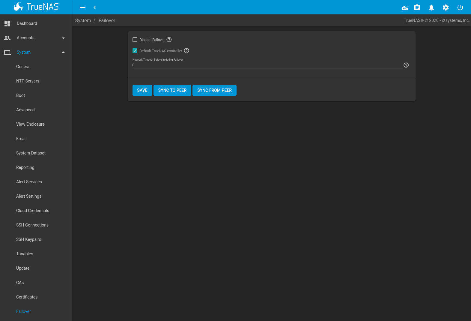
| Setting | Value | Description |
|---|---|---|
| Disabled | checkbox | Disables failover. Activates the Master checkbox. The HA Enabled icon changes to HA Disabled. An error message is generated if the standby TrueNAS controller is not responding or failover is not configured. |
| Master | checkbox | Only available when Disabled is set. Set to mark the current active TrueNAS controller as primary. The primary TrueNAS controller is the default active TrueNAS controller when both TrueNAS controllers are online and HA is enabled. To change which TrueNAS controller is primary, unset this option and allow TrueNAS® to fail over. This will briefly disrupt system services. |
| Timeout | integer | Number of seconds to wait after a network failure before triggering a failover. 0 indicates that a failover either occurs immediately or after two seconds when the system is using a link aggregation. |
| SYNC TO PEER | button | Force synchronizing the TrueNAS® configuration from the active TrueNAS controller to the standby TrueNAS controller. The standby TrueNAS controller must be rebooted after the synchronization is complete to load the new configuration. Synchronization occurs automatically in TrueNAS® and this option is only used when troubleshooting HA configurations. Do not use this unless requested by an iXsystems Support Engineer. |
| SYNC FROM PEER | button | Force synchronizing the TrueNAS® configuration from the standby TrueNAS controller to the active TrueNAS controller. Synchronization occurs automatically in TrueNAS® and this option is only used when troubleshooting HA configurations. Do not use this unless requested by an iXsystems Support Engineer. |
Notes about High Availability and failovers:
Booting an HA pair with failover disabled causes both TrueNAS controllers to come up in standby mode. The web interface shows an additional Force Takeover button which can be used to force that TrueNAS controller to take control.
Failover is not allowed if both TrueNAS controllers have the same CARP state. A critical Alert is generated and the HA icon shows HA Unavailable.
The TrueNAS® version of the ifconfig command adds two
additional fields to the output to help with failover troubleshooting:
CriticalGroupn and Interlink.
If both TrueNAS controllers reboot simultaneously, the GELI passphrase for an encrypted pool must be entered at the web interface login screen.
If there are a different number of disks connected to each TrueNAS controller, an Alert is generated and the HA icon switches to HA Unavailable.
5.19. Support
The TrueNAS® Support page, shown in Figure 5.19.1, is used to view or update the system license information, activate Proactive Support, or generate Support requests.
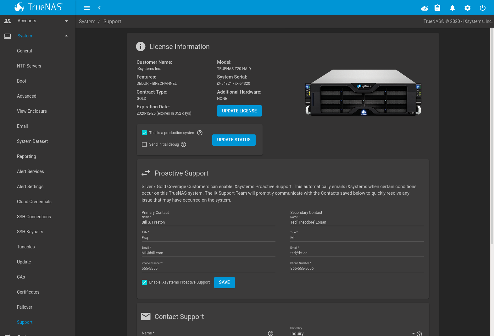
Fig. 5.19.1 Support Options
5.19.1. License Information
Systems with a valid license display the hardware model, system serial number, support contract type, licensed period, customer name, licensed features, and additional supported hardware.
If the license expires or additional hardware, features, or contract type are required, contact iXsystems Support. After a new license has been provided, click UPDATE LICENSE, paste in the new license, and click SAVE LICENSE. An additional dialog prompts to reload the web interface and show the new license details.
There are also options to mark the system for production use or to send an initial debug to iXsystems. To update the status, set either option and click UPDATE STATUS.
5.19.2. Proactive Support
The Proactive Support feature can notify iXsystems by email when hardware conditions on the system require attention.
Note
The fields on this tab are only enabled for Silver and Gold support coverage level customers. Please contact iXsystems for information on upgrading from other support levels.
Before enabling proactive support, provide primary and secondary contact information. This ensures iX Support can promptly communicate and quickly resolve any issues.
To enable proactive support, make sure all contact information is correct, set Enable iXsystems Proactive Support, and click SAVE.
5.19.3. Contact Support
To generate a support ticket, fill in the fields:
Name is the name of the person the iXsystems Support Representative should contact to assist with the issue.
Email is the email address of the person to contact.
Phone is the phone number of the person to contact.
Type is a drop-down menu to select the ticket type: a software bug, a hardware failure, a request for help with installing or configuring the system, or a request for help with diagnosing a performance bottleneck.
Environment is a drop-down menu to indicate the role of the affected system.
Table 5.19.1 Environment Options¶ Environment Description Production This is a production system in daily use. Staging The system is being prepared for production. Testing This system is only being used for testing purposes. Prototyping The system is unique. It is likely to be a proof of concept. Initial Deployment/ Setup This is a new system being prepared for deployment into production. Criticality is a drop-down menu to indicate how the issue has affected the TrueNAS® system. Choices are Inquiry, Loss of Functionality, or Total Down.
Attach Debug is an option to include an overview of the system hardware, build string, and configuration with the ticket. Generating and attaching a debug to the ticket can take some time.
Debug file attachments are limited to 20 MiB. If the debug file is too large to include, unset the option to generate the debug file and let the system create an issue ticket as shown below. Manually create a debug file by going to and clicking SAVE DEBUG.
Go to the ticket at iXsystems Support and upload the debug file.
Subject is a descriptive title for the ticket.
Description is a one- to three-paragraph summary of the issue that describes the problem, and if applicable, steps to reproduce it.
Attach screenshots is an optional field where screenshots of any errors or tracebacks can be included.
Click SUBMIT to generate and send the support ticket to iXsystems. This process can take several minutes while information is collected and sent. TrueNAS® sends an email alert if ticket creation fails while Proactive Support is active.
After the new ticket is created, the URL is shown for viewing or updating with more information. An iXsystems Support account is required to view the ticket. Click the URL to log in or register with the support portal. Use the same e-mail address submitted with the ticket when registering.
UPDATE LICENSE functions identically to the button in the License Information section.
USER GUIDE opens a new browser tab to the iXsystems TrueNAS® Information Library. The TrueNAS® User Guide, product datasheets, TrueNAS® hardware setup guides, and task assistance articles are all available in this library.
EULA shows the TrueNAS® End User License Agreement.