2. Initial Setup
2.1. Hardware Setup
Basic Setup Guides for TrueNAS® systems and expansion shelves are included with the hardware and also available in the iX Information Library. These guides provide detailed instructions on included components, controls, ports, rack installation, drive loading, and cable connections.
Complete hardware installation before continuing.
Note
Always perform the initial TrueNAS® setup in consultation
with your iXsystems Support Representative. iXsystems Support can
be contacted at truenas-support@ixsystems.com. Be sure
to have all TrueNAS® hardware serial numbers on hand. The serial
numbers are located on the back of each chassis.
2.2. Console Setup Menu
The Console Setup menu, shown in Figure 2.2.1, appears at the end of the boot process. If the TrueNAS® system has a keyboard and monitor, this Console Setup menu can be used to administer the system.
Note
When connecting to the TrueNAS® system with SSH or the web
Shell, the Console Setup menu is not shown by default.
It can be started by the root user or another user with root
permissions by typing /etc/netcli.
The Console Setup menu can be disabled by unchecking Enable Console Menu in .
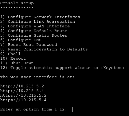
Fig. 2.2.1 Console Setup Menu
Note
On HA systems, some of these menu options are not available unless HA has been administratively disabled.
The menu provides these options:
1) Configure Network Interfaces provides a configuration wizard to set up the system’s network interfaces. If the system has been licensed for High Availability (HA), the wizard prompts for IP addresses for both “This Controller” and “TrueNAS Controller 2”.
2) Configure Link Aggregation is for creating or deleting link aggregations.
3) Configure VLAN Interface is used to create or delete VLAN interfaces.
4) Configure Default Route is used to set the IPv4 or IPv6 default gateway. When prompted, enter the IP address of the default gateway.
5) Configure Static Routes prompts for the destination network and gateway IP address. Re-enter this option for each static route needed.
6) Configure DNS prompts for the name of the DNS domain
and the IP address of the first DNS server. When adding multiple DNS
servers, press Enter to enter the next one. Press Enter
twice to leave this option.
7) Reset Root Password is used to reset a lost or
forgotten root password. Select this option and follow the
prompts to set the password.
8) Reset Configuration to Defaults Caution! This option deletes all of the configuration settings made in the administrative GUI and is used to reset a TrueNAS® system back to defaults. Before selecting this option, make a full backup of all data and make sure all encryption keys and passphrases are known! After this option is selected, the configuration is reset to defaults and the system reboots. can be used to re-import pools.
9) Shell starts a shell for running FreeBSD commands. To leave the shell, type exit.
10) Reboot reboots the system.
11) Shut Down shuts down the system.
Note
The numbering and quantity of options on this menu can change due to software updates, service agreements, or other factors. Please carefully check the menu before selecting an option, and keep this in mind when writing local procedures.
During boot, TrueNAS® automatically attempts to connect to a DHCP server from all live interfaces. If it successfully receives an IP address, the address is displayed so it can be used to access the graphical user interface. In the example seen in Figure 2.2.1, the TrueNAS® system is accessible at http://10.0.0.102.
Some TrueNAS® systems are set up without a monitor, making it challenging to determine which IP address has been assigned. On networks that support Multicast DNS (mDNS), the hostname and domain can be entered into the address bar of a browser. By default, this value is truenas.local.
If the TrueNAS® server is not connected to a network with a DHCP server, use the console network configuration menu to manually configure the interface as shown here. In this example, the TrueNAS® system has one network interface, em0.
Enter an option from 1-12: 1
1) em0
Select an interface (q to quit): 1
Remove the current settings of this interface? (This causes a momentary disconnec
tion of the network.) (y/n) n
Configure interface for DHCP? (y/n) n
Configure IPv4? (y/n) y
Interface name:     (press enter, the name can be blank)
Several input formats are supported
Example 1 CIDR Notation:
    192.168.1.1/24
Example 2 IP and Netmask separate:
    IP: 192.168.1.1
    Netmask: 255.255.255.0, or /24 or 24
IPv4 Address: 192.168.1.108/24
Saving interface configuration: Ok
Configure IPv6? (y/n) n
Restarting network: ok

...

The web user interface is at
http://192.168.1.108
2.3. Accessing the Web Interface
The IP address of the TrueNAS® graphical web interface is provided on the TrueNAS® sales order or configuration sheet. Please contact iX Support if the TrueNAS® web interface IP address has not been provided with these documents or cannot be identified from the TrueNAS® system console.
On a computer that can access the same network as the TrueNAS® system, enter the IP address in a web browser to connect to the web interface. The password for the root user is requested.
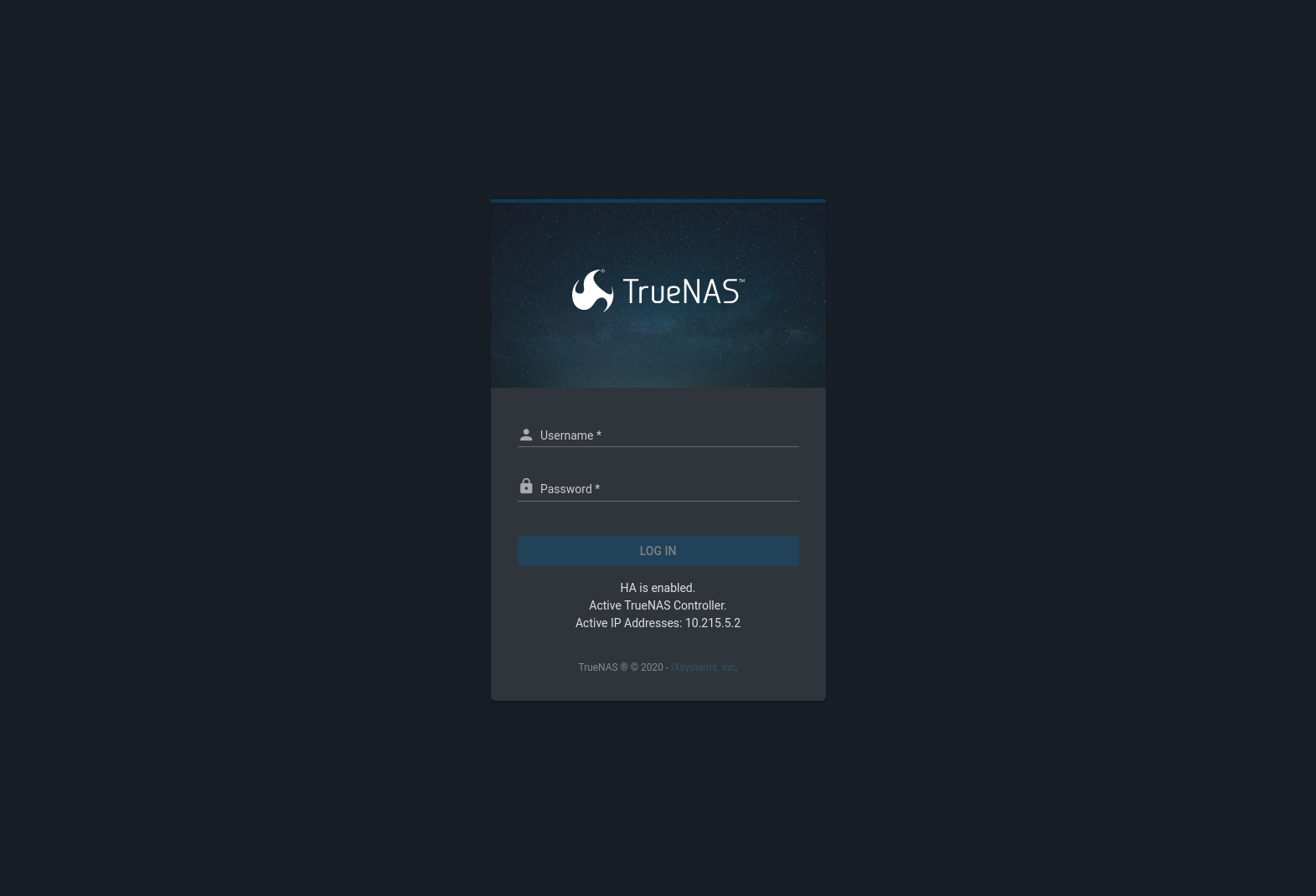
Fig. 2.3.1 Login Screen
The High Availability (HA) status and information about the active TrueNAS controller is displayed on this screen. Log in with:
- Username:
root - Password:
abcd1234
Note
The default root password can be changed to a more secure value by going to . Expand the entry for root and click EDIT. Enter the new password in the Password and Confirm Password fields and click SAVE. The new password is used for subsequent logins.
On the first login, the EULA found in Appendix A: End-User License Agreement is displayed, along with a box where the license key for the TrueNAS® array can be pasted. Read the EULA and paste in the license key. High Availability (HA) systems must have both active and standby TrueNAS controllers running before the license key for the HA TrueNAS® system can be entered. The key is entered on the active TrueNAS controller. Click OK to save the license key and access the web interface.
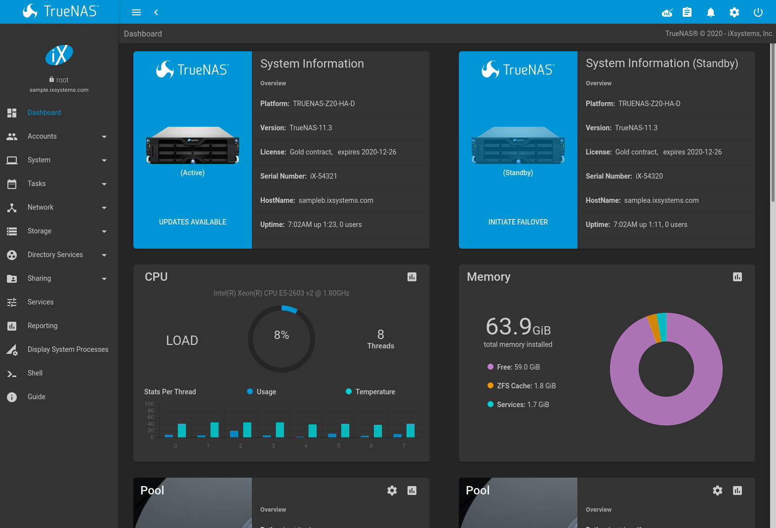
Fig. 2.3.2 Dashboard
The shows details about the system. These details are grouped into sections about the hardware components, networking, storage, and other categories.
2.3.1. Web Interface Troubleshooting
If the user interface is not accessible by IP address from a browser, check these things:
- Are proxy settings enabled in the browser configuration? If so, disable the settings and try connecting again.
- If the page does not load, make sure that a ping reaches the TrueNAS® system’s IP address. If the address is in a private IP address range, it is only accessible from within that private network.
If the UI becomes unresponsive after an upgrade or other system operation, clear the site data and refresh the browser.
The rest of this User Guide describes the TrueNAS® web interface in more detail. The layout of this User Guide follows the order of the menu items in the tree located in the left frame of the web interface.
Please contact iXsystems Support for initial setup and configuration assistance.
Warning
It is important to use the web interface or the console setup menu for all configuration changes. Do not make changes from the command line unless directed by an iXsystems Support Engineer.