8. Network
The Network section of the web interface contains these components for viewing and configuring network settings on the FreeNAS® system:
- Global Configuration: general network settings.
- Interfaces: settings for each network interface.
- IPMI: settings controlling connection to the appliance through the hardware side-band management interface if the user interface becomes unavailable.
- Link Aggregations: settings for network link aggregation and link failover.
- Static Routes: add static routes.
- VLANs: configure IEEE 802.1q tagging for virtual LANs.
Each of these is described in more detail in this section.
Warning
Making changes to the network interface the web interface uses can result in losing connection to the FreeNAS® system! Misconfiguring network settings might require command line knowledge or physical access to the FreeNAS® system to fix. Be very careful when configuring Interfaces and Link Aggregations.
8.1. Global Configuration
, shown in Figure 8.1.1, is for general network settings that are not unique to any particular network interface.
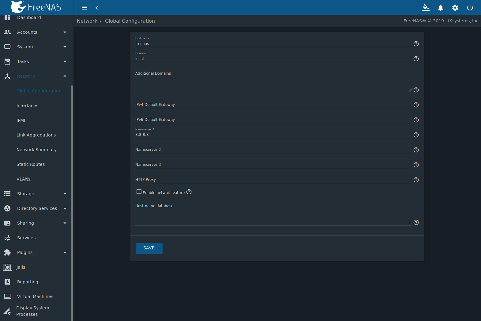
Fig. 8.1.1 Global Network Configuration
Table 8.1.1 summarizes the settings on the Global Configuration tab. Hostname and Domain fields are pre-filled as shown in Figure 8.1.1, but can be changed to meet requirements of the local network.
| Setting | Value | Description |
|---|---|---|
| Hostname | string | System host name. Cannot contain the underscore character. |
| Domain | string | System domain name. |
| Additional Domains | string | Additional space-delimited domains to search. Adding search domains can cause slow DNS lookups. |
| IPv4 Default Gateway | IP address | Typically not set. See this note about Gateways. If set, used instead of the default gateway provided by DHCP. |
| IPv6 Default Gateway | IP address | Typically not set. See this note about Gateways. |
| Nameserver 1 | IP address | Primary DNS server. |
| Nameserver 2 | IP address | Secondary DNS server. |
| Nameserver 3 | IP address | Tertiary DNS server. |
| HTTP Proxy | string | Enter the proxy information for the network in the format http://my.proxy.server:3128 or http://user:password@my.proxy.server:3128. |
| Enable netwait feature | checkbox | If enabled, network services do not start at boot until the interface is able to ping the addresses listed in the Netwait IP list. |
| Netwait IP list | string | Only appears when Enable netwait feature is set. Enter a space-delimited list of IP addresses to ping(8). Each address is tried until one is successful or the list is exhausted. Leave empty to use the default gateway. |
| Host name database | string | Used to add one entry per line which will be appended to /etc/hosts. Use the format
IP_address space hostname where multiple hostnames can be used if separated by a space. |
When using Active Directory, set the IP address of the realm DNS server in the Nameserver 1 field.
If the network does not have a DNS server, or NFS, SSH, or FTP users are receiving “reverse DNS” or timeout errors, add an entry for the IP address of the FreeNAS® system in the Host name database field.
Note
In many cases, a FreeNAS® configuration does not include default gateway information as a way to make it more difficult for a remote attacker to communicate with the server. While this is a reasonable precaution, such a configuration does not restrict inbound traffic from sources within the local network. However, omitting a default gateway will prevent the FreeNAS® system from communicating with DNS servers, time servers, and mail servers that are located outside of the local network. In this case, it is recommended to add Static Routes to be able to reach external DNS, NTP, and mail servers which are configured with static IP addresses. When a gateway to the Internet is added, make sure the FreeNAS® system is protected by a properly configured firewall.
8.2. Interfaces
shows which interfaces are manually configured and allows adding or editing a manually configured interface.
See this warning about changing the interface that the web interface uses.
Figure 8.2.1 shows the screen that appears after clicking ADD from the Interfaces page. Table 8.2.1 summarizes the configuration options shown when adding an interface or editing an existing interface.
Note
An interface can only be added when there is a NIC that has
not already been configured. Clicking ADD when there are no
NICs available will display a message across the bottom of the screen
that All interfaces are already in use..
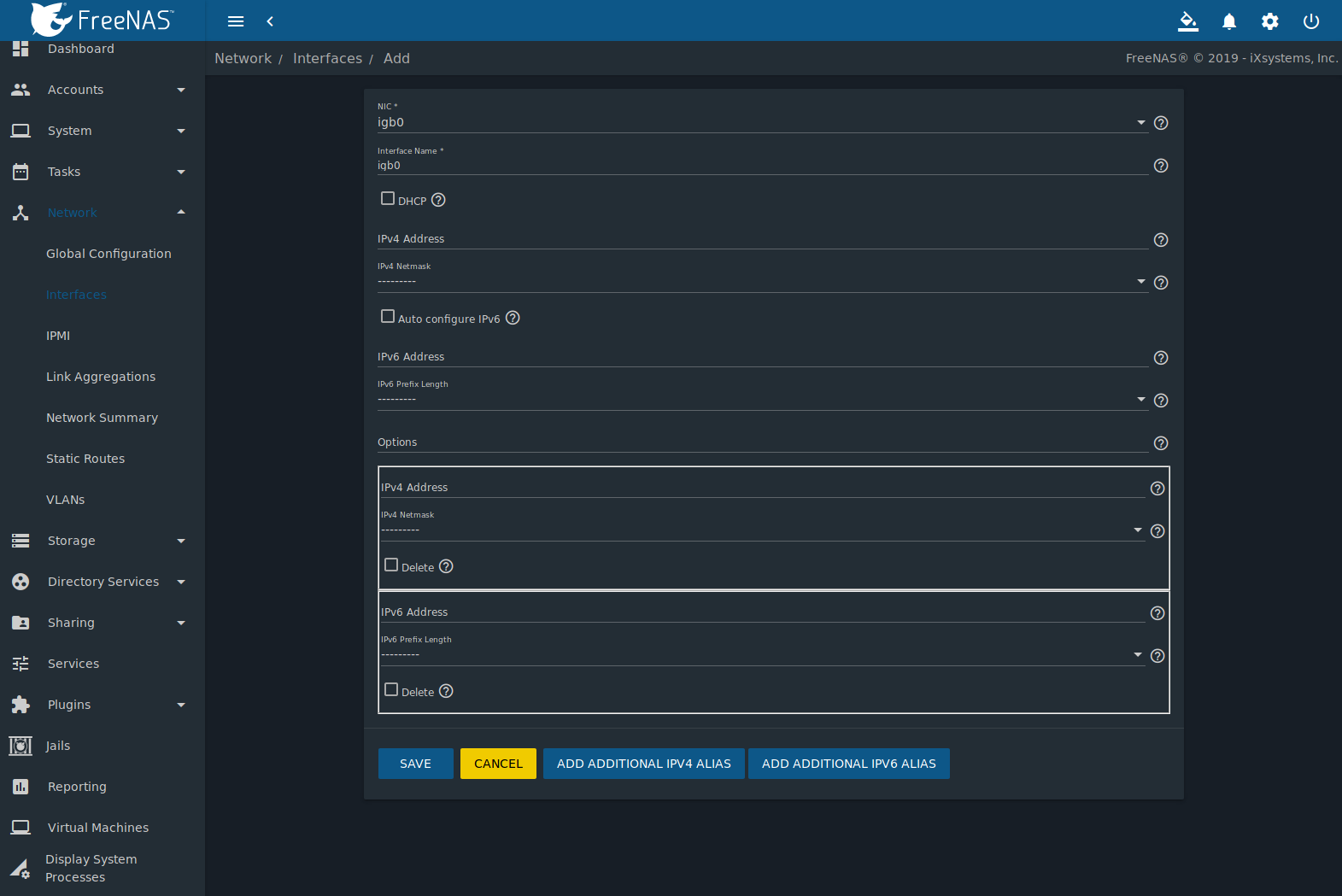
Fig. 8.2.1 Adding or Editing an Interface
| Setting | Value | Description |
|---|---|---|
| NIC | drop-down menu | The FreeBSD device name of the interface. This is read-only when editing an interface. |
| Interface Name | string | Description of interface. |
| DHCP | checkbox | Requires static IPv4 or IPv6 configuration if unselected. Only one interface can be configured for DHCP. |
| IPv4 Address | IP address | Enter a static IP address if DHCP is unset. |
| IPv4 Netmask | drop-down menu | Enter a netmask if DHCP is unset. |
| Auto configure IPv6 | checkbox | Only one interface can be configured for this option. If unset, manual configuration is required to use IPv6. |
| IPv6 Address | IPv6 address | Must be unique on the network. |
| IPv6 Prefix Length | drop-down menu | Match the prefix used on the network. |
| Options | string | Additional parameters from ifconfig(8). Separate multiple parameters with a space. For example: mtu 9000 increases the MTU for interfaces which support jumbo frames. See this note about MTU and lagg interfaces. |
Multiple interfaces cannot be members of the same subnet. See Multiple network interfaces on a single subnet for more information. Check the subnet mask if an error is shown when setting the IP addresses on multiple interfaces.
Set only the IPv4 or IPv6 address for the new interface.
8.3. IPMI
Beginning with version 9.2.1, FreeNAS® provides a graphical screen for configuring an IPMI interface. This screen will only appear if the system hardware includes a Baseboard Management Controller (BMC).
IPMI provides side-band management if the graphical administrative interface becomes unresponsive. This allows for a few vital functions, such as checking the log, accessing the BIOS setup, and powering on the system without requiring physical access to the system. IPMI is also used to give another person remote access to the system to assist with a configuration or troubleshooting issue. Before configuring IPMI, ensure that the management interface is physically connected to the network. The IPMI device may share the primary Ethernet interface, or it may be a dedicated separate IPMI interface.
Warning
It is recommended to first ensure that the IPMI has been patched against the Remote Management Vulnerability before enabling IPMI. This article provides more information about the vulnerability and how to fix it.
Note
Some IPMI implementations require updates to work with newer versions of Java. See PSA: Java 8 Update 131 breaks ASRock’s IPMI Virtual console for more information.
IPMI is configured from . The IPMI configuration screen, shown in Figure 8.3.1, provides a shortcut to the most basic IPMI configuration. Those already familiar with IPMI management tools can use them instead. Table 8.3.1 summarizes the options available when configuring IPMI with the FreeNAS® web interface.
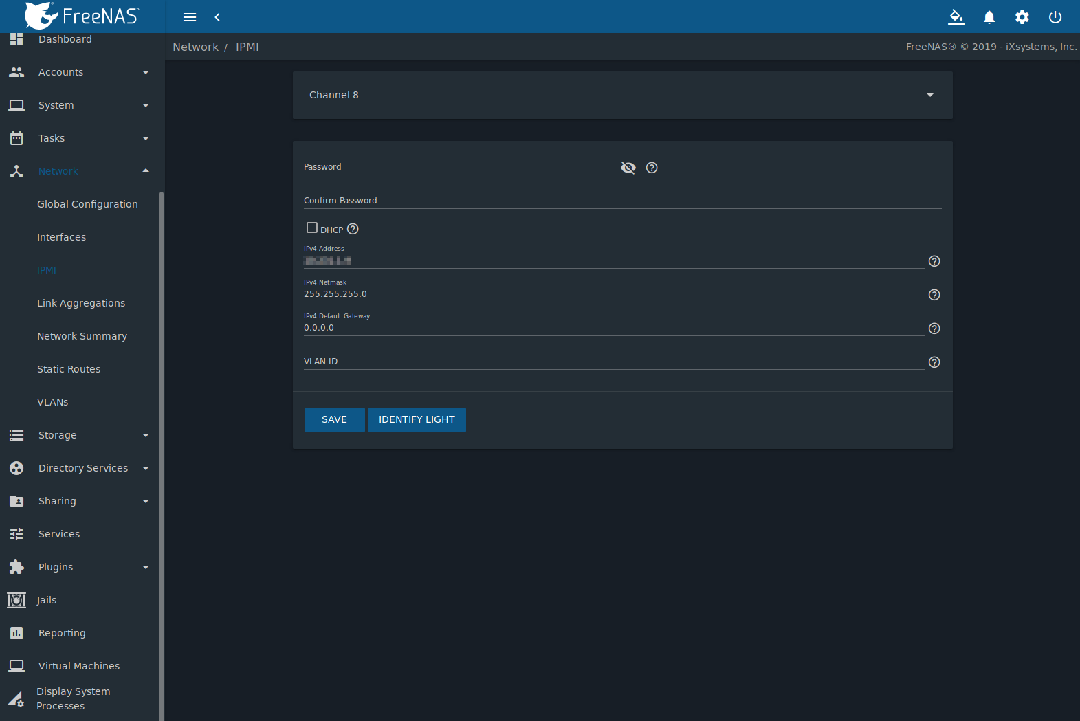
Fig. 8.3.1 IPMI Configuration
| Setting | Value | Description |
|---|---|---|
| Channel | drop-down menu | Select the channel to use. |
| Password | string | Enter the password used to connect to the IPMI interface from a web browser. The maximum length is 20 characters. |
| DHCP | checkbox | If left unset, IPv4 Address, IPv4 Netmask, and Ipv4 Default Gateway must be set. |
| IPv4 Address | string | IP address used to connect to the IPMI web interface. |
| IPv4 Netmask | drop-down menu | Subnet mask associated with the IP address. |
| IPv4 Default Gateway | string | Default gateway associated with the IP address. |
| VLAN ID | string | Enter the VLAN identifier if the IPMI out-of-band management interface is not on the same VLAN as management networking. |
After configuration, the IPMI interface is accessed using a web browser and the IP address specified in the configuration. The management interface prompts for a username and the configured password. Refer to the IPMI device documentation to determine the default administrative username.
After logging in to the management interface, the default administrative username can be changed, and additional users created. The appearance of the IPMI utility and the functions that are available vary depending on the hardware.
A command-line utility called ipmitool is available to control many features of the IPMI interface. See How To: Change IPMI Sensor Thresholds using ipmitool for some examples.
8.4. Link Aggregations
FreeNAS® uses the FreeBSD lagg(4) interface to provide link aggregation and link failover support. A lagg interface allows combining multiple network interfaces into a single virtual interface. This provides fault-tolerance and high-speed multi-link throughput. The aggregation protocols supported by lagg both determines the ports to use for outgoing traffic and if a specific port accepts incoming traffic. The link state of the lagg interface is used to validate whether the port is active.
Aggregation works best on switches supporting LACP, which distributes traffic bi-directionally while responding to failure of individual links. FreeNAS® also supports active/passive failover between pairs of links. The LACP and load-balance modes select the output interface using a hash that includes the Ethernet source and destination address, VLAN tag (if available), IP source and destination address, and flow label (IPv6 only). The benefit can only be observed when multiple clients are transferring files from the NAS. The flow entering into the NAS depends on the Ethernet switch load-balance algorithm.
The lagg driver currently supports several aggregation protocols, although only Failover is recommended on network switches that do not support LACP:
Failover: the default protocol. Sends traffic only through the active port. If the master port becomes unavailable, the next active port is used. The first interface added is the master port. Any interfaces added later are used as failover devices. By default, received traffic is only accepted when received through the active port. This constraint can be relaxed, which is useful for certain bridged network setups, by going to and clicking ADD to add a tunable. Set the Variable to net.link.lagg.failover_rx_all, the Value to a non-zero integer, and the Type to Sysctl.
LACP: supports the IEEE 802.3ad Link Aggregation Control Protocol (LACP) and the Marker Protocol. LACP negotiates a set of aggregable links with the peer into one or more link aggregated groups (LAGs). Each LAG is composed of ports of the same speed, set to full-duplex operation. Traffic is balanced across the ports in the LAG with the greatest total speed. In most situations there will be a single LAG which contains all ports. In the event of changes in physical connectivity, link aggregation quickly converges to a new configuration. LACP must be configured on the network switch and LACP does not support mixing interfaces of different speeds. Only interfaces that use the same driver, like two igb ports, are recommended for LACP. Using LACP for iSCSI is not recommended as iSCSI has built-in multipath features which are more efficient.
Note
When using LACP, verify the switch is configured for active LACP. Passive LACP is not supported.
Load Balance: balances outgoing traffic across the active ports based on hashed protocol header information and accepts incoming traffic from any active port. This is a static setup and does not negotiate aggregation with the peer or exchange frames to monitor the link. The hash includes the Ethernet source and destination address, VLAN tag (if available), and IP source and destination address. Requires a switch which supports IEEE 802.3ad static link aggregation.
Round Robin: distributes outgoing traffic using a round-robin scheduler through all active ports and accepts incoming traffic from any active port. This mode can cause unordered packet arrival at the client. This has a side effect of limiting throughput as reordering packets can be CPU intensive on the client. Requires a switch which supports IEEE 802.3ad static link aggregation.
None: this protocol disables any traffic without disabling the lagg interface itself.
8.4.1. LACP, MPIO, NFS, and ESXi
LACP bonds Ethernet connections to improve bandwidth. For example, four physical interfaces can be used to create one mega interface. However, it cannot increase the bandwidth for a single conversation. It is designed to increase bandwidth when multiple clients are simultaneously accessing the same system. It also assumes that quality Ethernet hardware is used and it will not make much difference when using inferior Ethernet chipsets such as a Realtek.
LACP reads the sender and receiver IP addresses and, if they are deemed to belong to the same TCP connection, always sends the packet over the same interface to ensure that TCP does not need to reorder packets. This makes LACP ideal for load balancing many simultaneous TCP connections, but does nothing for increasing the speed over one TCP connection.
MPIO operates at the iSCSI protocol level. For example, if four IP addresses are created and there are four simultaneous TCP connections, MPIO will send the data over all available links. When configuring MPIO, make sure that the IP addresses on the interfaces are configured to be on separate subnets with non-overlapping netmasks, or configure static routes to do point-to-point communication. Otherwise, all packets will pass through one interface.
LACP and other forms of link aggregation generally do not work well with virtualization solutions. In a virtualized environment, consider the use of iSCSI MPIO through the creation of an iSCSI Portal with at least two network cards on different networks. This allows an iSCSI initiator to recognize multiple links to a target, using them for increased bandwidth or redundancy. This how-to contains instructions for configuring MPIO on ESXi.
NFS does not understand MPIO. Therefore, one fast interface is needed, since creating an iSCSI portal will not improve bandwidth when using NFS. LACP does not work well to increase the bandwidth for point-to-point NFS (one server and one client). LACP is a good solution for link redundancy or for one server and many clients.
8.4.2. Creating a Link Aggregation
Before creating a link aggregation, make sure that all interfaces to use in the lagg are not manually configured in . Lagg creation fails if any of the included interfaces are manually configured. See this warning about changing the interface that the web interface uses.
To create a link aggregation, go to and click ADD. Figure 8.4.1 shows the configuration options.
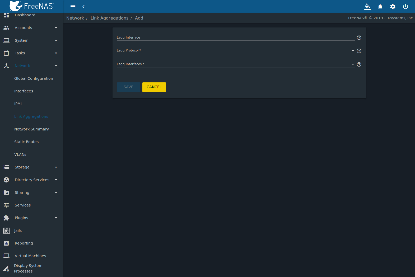
Fig. 8.4.1 Creating a Link Aggregation
Enter a descriptive name for the Lagg Interface. Next, select the desired Lagg Protocol. LACP is preferred. Choose Failover when the network switch does not support LACP. Choose interfaces from the Lagg Interfaces drop-down menu to associate NICs with the lagg device and then click the SAVE button to save the new aggregation.
Note
If interfaces are installed but do not appear in the Lagg Interfaces list, check for a FreeBSD driver for the interface.
After creating the link aggregation, go to and click (Options) for the new lagg to view options to Edit Interface, Edit Members, and Delete.
Clicking Edit Interface for a lagg opens the configuration screen shown in Figure 8.4.2. Table 8.4.1 describes the options in this screen.
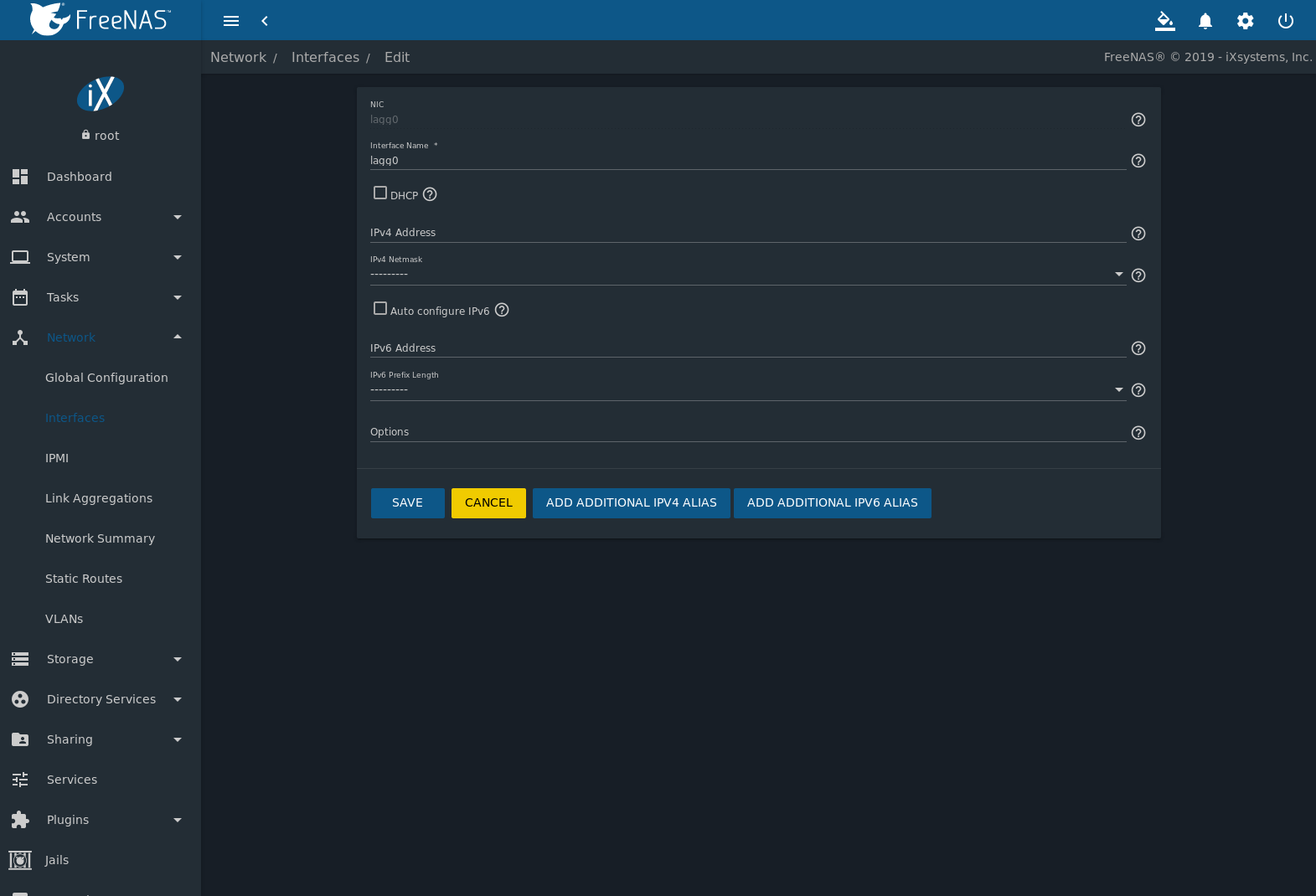
Fig. 8.4.2 Editing a lagg
| Setting | Value | Description |
|---|---|---|
| NIC | string | Read-only. Automatically assigned the next available numeric ID. |
| Interface Name | string | By default, this is the same as NIC. This can be changed to a more descriptive value. |
| DHCP | checkbox | Enable if the lagg device will get IP address info from DHCP server. The IP address of the new lagg can be set to DHCP only if no other interface uses DHCP. |
| IPv4 Address | string | Enter a static IP address if DHCP is unset. |
| IPv4 Netmask | drop-down menu | Enter a netmask if DHCP is left unset. |
| Auto configure IPv6 | checkbox | Set only if a DHCP server is available to provide IPv6 address information. |
| IPv6 Address | string | Optional. |
| IPv6 Prefix Length | drop-down menu | Required if an IPv6 address is entered. |
| Options | string | Additional ifconfig(8) options. |
There are also buttons to add and remove extra IPv4 or IPv6 aliases.
In , click (Options) and Edit Members for a lagg to see the Members screen, shown in Figure 8.4.3.
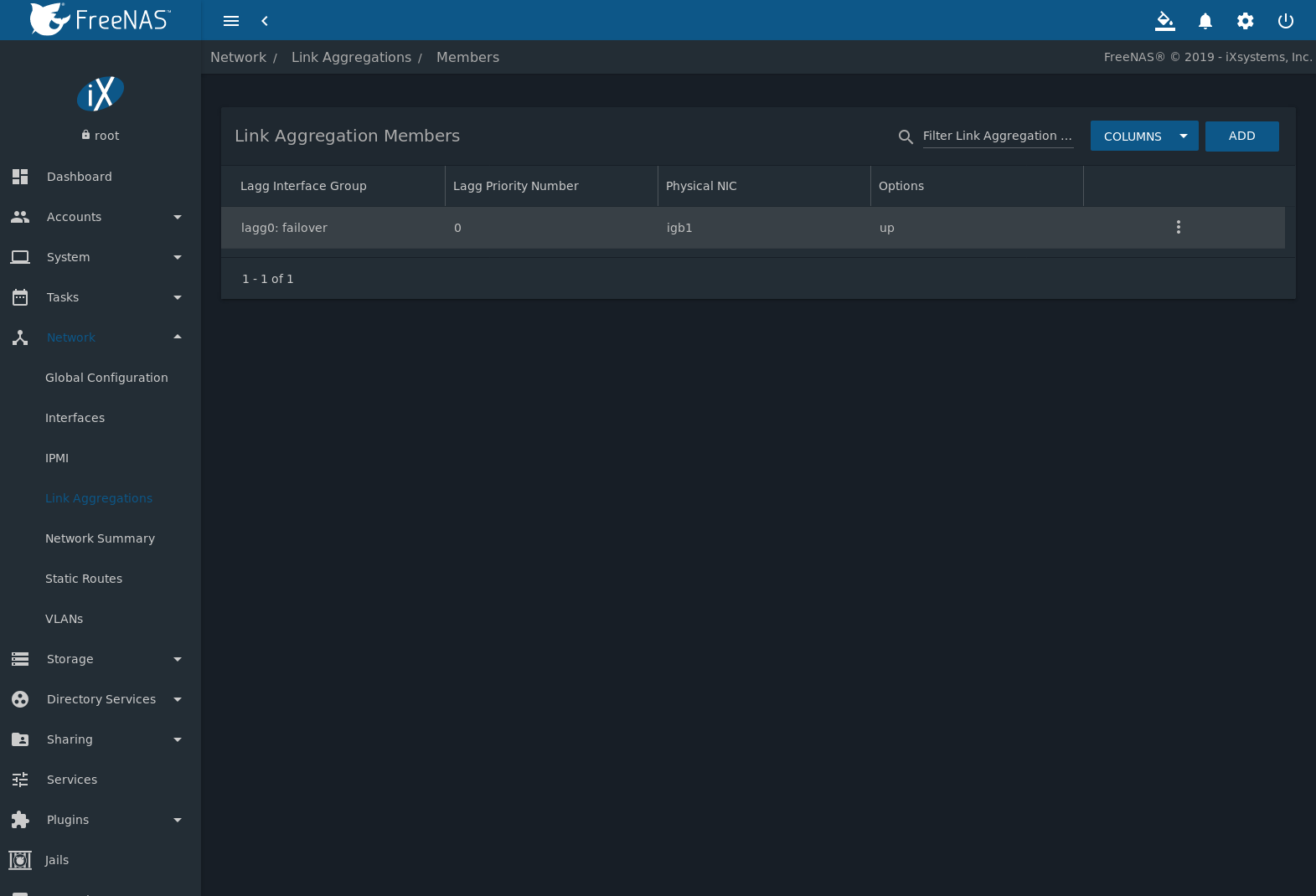
Fig. 8.4.3 Link Aggregation Members
Click (Options) for an existing lagg member to see options to Edit and Delete it. Choose Edit to adjust an existing member. The configurable options are summarized in Table 8.4.2.
| Setting | Value | Description |
|---|---|---|
| LAGG Interface Group | drop-down menu | Select the member interface to configure. |
| LAGG Priority Number | integer | Order of selected interface within the lagg. Configure a failover to set the master interface to 0 and the other interfaces to 1, 2, etc. |
| LAGG Physical NIC | drop-down menu | Physical interface of the selected member. This field only appears when a NIC is available. |
| Options | string | Additional parameters from ifconfig(8). |
Click ADD to open the screen shown in Figure 8.4.4.
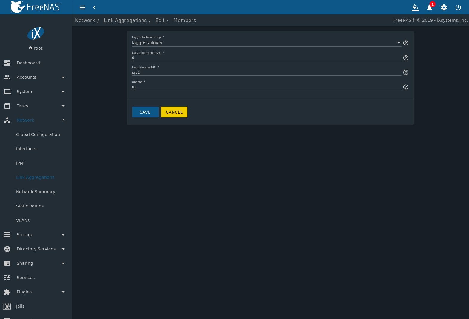
Fig. 8.4.4 Add Link Aggregation Member
The options are identical to the Configuring a Member Interface table. Click SAVE to add the member to the list in .
8.4.3. Link Aggregation Options
Options are set at the lagg level from the page. Click (Options) and Edit Members for an existing lagg interface. Click (Options) and Edit for the existing member. Scroll to the Options field.
To set options at the individual parent interface level, go to , and click (Options) on the desired interface. Select Edit, and scroll to the Options field. Changes are typically made at the lagg level as each interface member inherits settings from the lagg. Configuring at the interface level requires repeating the configuration for each interface within the lagg.
Some options can only be set on the parent interfaces and are inherited by the lagg interface. For example, to set the MTU on a lagg, go to , click (Options), and then Edit to set the MTU for each parent interface.
If the MTU settings on the lagg member interfaces are not identical, the smallest value is used for the MTU of the entire lagg.
Note
A reboot is required after changing the MTU to create a jumbo frame lagg.
Link aggregation load balancing can be tested with:
systat -ifstat
More information about this command can be found at systat(1).
8.5. Network Summary
shows a quick summary of the addressing information of every configured interface. For each interface name, the configured IPv4 and IPv6 addresses, default routes, and DNS namerservers are displayed.
8.6. Static Routes
No static routes are defined on a default FreeNAS® system. If a static route is required to reach portions of the network, add the route by going to , and clicking ADD. This is shown in Figure 8.6.1.
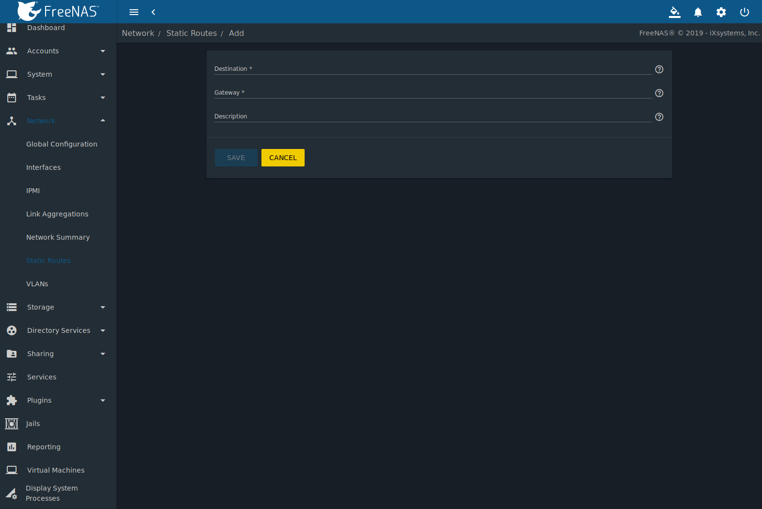
Fig. 8.6.1 Adding a Static Route
The available options are summarized in Table 8.6.1.
| Setting | Value | Description |
|---|---|---|
| Destination | integer | Use the format A.B.C.D/E where E is the CIDR mask. |
| Gateway | integer | Enter the IP address of the gateway. |
| Description | string | Optional. Add any notes about the route. |
Added static routes are shown in . Click (Options) on a route entry to access the Edit and Delete buttons.
8.7. VLANs
FreeNAS® uses FreeBSD’s vlan(4) interface to demultiplex frames with IEEE 802.1q tags. This allows nodes on different VLANs to communicate through a layer 3 switch or router. A vlan interface must be assigned a parent interface and a numeric VLAN tag. A single parent can be assigned to multiple vlan interfaces provided they have different tags.
Note
VLAN tagging is the only 802.1q feature that is implemented. Additionally, not all Ethernet interfaces support full VLAN processing. See the HARDWARE section of vlan(4) for details.
Go to and click ADD to see the screen shown in Figure 8.7.1.
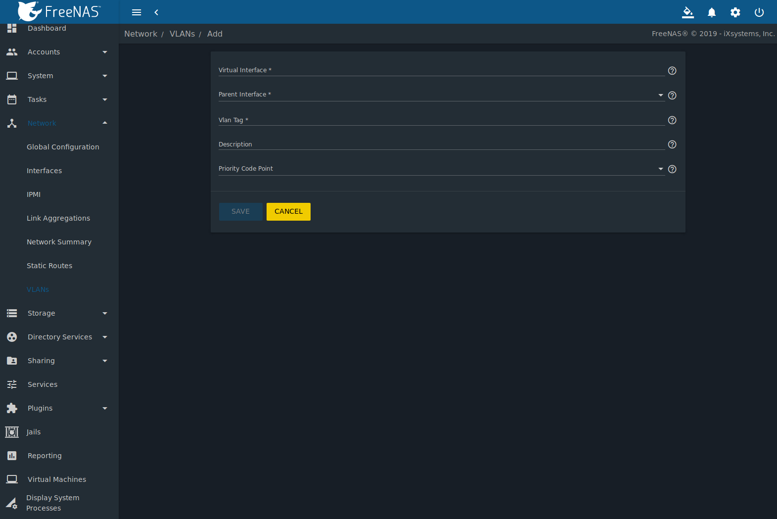
Fig. 8.7.1 Adding a VLAN
Table 8.7.1 summarizes the configurable fields.
| Setting | Value | Description |
|---|---|---|
| Virtual Interface | string | Use the format vlanX where X is a number representing a VLAN interface not currently being used as a parent. |
| Parent Interface | drop-down menu | Usually an Ethernet card connected to a properly configured switch port. Newly created Link Aggregations do not appear in the drop-down until the system is rebooted. |
| Vlan Tag | integer | Enter a number between 1 and 4095 which matches a numeric tag set up in the switched network. |
| Description | string | Optional. Enter any notes about this VLAN. |
| Priority Code Point | drop-down menu | Available 802.1p Class of Service ranges from Best Effort (default) to Network Control (highest). |
The parent interface of a VLAN must be up, but it can either have an IP address or be unconfigured, depending upon the requirements of the VLAN configuration. This makes it difficult for the web interface to do the right thing without trampling the configuration. To remedy this, add the VLAN, then select , and click ADD. Choose the parent interface from the NIC drop-down menu and in the Options field, type up. This brings up the parent interface. If an IP address is required, configure it using the rest of the options in the ADD screen.
Warning
Creating a VLAN causes an interruption to network connectivity. The web interface provides a warning about this interruption.