16. Virtual Machines
A Virtual Machine (VM) is an environment on a host computer that can be used as if it were a separate physical computer. VMs can be used to run multiple operating systems simultaneously on a single computer. Operating systems running inside a VM see emulated virtual hardware rather than the actual hardware of the host computer. This provides more isolation than Jails, although there is additional overhead. A portion of system RAM is assigned to each VM, and each VM uses a zvol for storage. While a VM is running, these resources are not available to the host computer or other VMs.
FreeNAS® VMs use the bhyve(8) virtual machine software. This type of virtualization requires an Intel processor with Extended Page Tables (EPT) or an AMD processor with Rapid Virtualization Indexing (RVI) or Nested Page Tables (NPT).
To verify that an Intel processor has the required features, use
Shell to run grep VT-x /var/run/dmesg.boot. If the
EPT and UG features are shown, this processor can be used with
bhyve.
To verify that an AMD processor has the required features, use Shell to run grep POPCNT /var/run/dmesg.boot. If the output shows the POPCNT feature, this processor can be used with bhyve.
Note
AMD K10 “Kuma” processors include POPCNT but do not support NRIPS, which is required for use with bhyve. Production of these processors ceased in 2012 or 2013.
By default, new VMs have the
bhyve(8)
-H option set. This causes the virtual CPU thread to yield
when a HLT instruction is detected and prevents idle VMs from consuming
all of the host CPU.
shows a list of installed virtual machines.
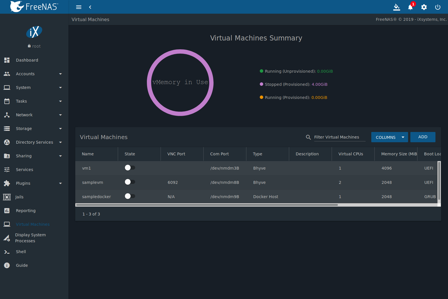
Fig. 16.1 Virtual Machines
The (Options) menu has options for controlling and modifying VMs:
Start boots a VM. VMs can also be started by clicking the slide toggle on the desired VM.
An option is provided to Overcommit Memory. Memory overcommitment allows multiple VMs to be launched when there is not enough free memory for all of them to run at the same time. This option should be used with caution.
When active, the VM State changes to RUNNING. To start a VM when the host system boots, set Autostart.
Edit changes VM settings.
Delete removes the VM. Zvols used in disk devices and image files used in raw file devices are not removed when a VM is deleted. These resources can be removed manually in after it is determined that the data in them has been backed up or is no longer needed.
Devices is used to add, remove, or edit devices attached to a virtual machine.
Clone copies the VM. The new clone has
_cloneNappended to the name, whereNis the clone number.
These additional options in (Options) are available when a VM is running:
Power off immediately halts the VM. This is equivalent to unplugging the power cord from a computer.
Stop shuts down the VM.
Restart shuts down and immediately starts the VM.
VMs with Web Interface enabled show a VNC button. VNC connections permit remote graphical access to the VM.
Serial opens a connection to a virtual serial port on the VM.
/dev/nmdm1Bis assigned to the first VM,/dev/nmdm2Bis assigned to the second VM, and so on. These virtual serial ports allow connections to the VM console from the Shell.Tip
The nmdm device is dynamically created. The actual
nmdm XYname varies on each VM.To connect to the first VM, type
cu -l /dev/nmdm1B -s 9600in the Shell. See cu(1) for more information.
16.1. Creating VMs
Click ADD to open the wizard in Figure 16.1.1:
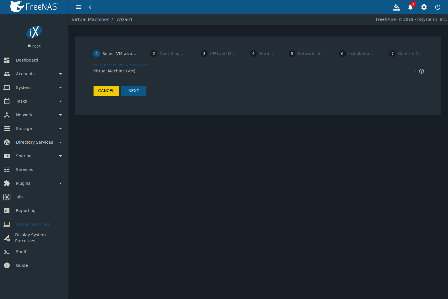
Fig. 16.1.1 Add VM
Select a virtual machine type from the Virtual Machine (VM) Wizard type. The choices are Virtual Machine (VM) and Docker Host.
The configuration options for a Virtual Machine (VM) type are described in Table 16.1.1.
| Screen # | Setting | Value | Description |
|---|---|---|---|
| 1 | Virtual Machine (VM) Wizard type | drop-down menu | Select the type of VM to create. |
| 2 | Guest Operating System | drop-down menu | Choose the VM operating system type. Choices are: Windows, Linux, or FreeBSD. See this guide for detailed instructions about using a different guest OS. |
| 2 | Name | string | Name of the VM. Alphanumeric characters and _ are allowed. The name must be
unique. |
| 2 | Boot Method | drop-down menu | Select UEFI for newer operating systems, or UEFI-CSM (Compatibility Support Mode) for older operating systems that only understand BIOS booting. VNC connections are only available with UEFI. |
| 2 | Start on Boot | checkbox | Set to start the VM when the system boots. |
| 2 | Enable VNC | checkbox | Add a VNC remote connection. Requires UEFI booting. |
| 2 | Bind | drop-down menu | VNC network interface IP address. The primary interface IP address is the default. A different interface IP address can be chosen. |
| 3 | Virtual CPUs | integer | Number of virtual CPUs to allocate to the VM. The maximum is 16 unless limited by the host CPU. The VM operating system might also have operational or licensing restrictions on the number of CPUs. |
| 3 | Memory Size (MiB) | integer | Allocate the amount of RAM in mebibytes for the VM. |
| 4 | Disk image | check option with custom fields | Select Create new disk image to create a new zvol on an existing dataset. This is used as a virtual hard drive for the VM. Select Use existing disk image and choose an existing zvol from the Select Existing zvol drop-down. |
| 4 | Select Disk Type | drop-down menu | Select the disk type. Choices are AHCI and VirtIO. Refer to Disk Devices for more information about these disk types. |
| 4 | Size (GiB) | integer | Allocate the amount of storage in GiB for the new zvol. |
| 4 | Select zvol | drop-down menu | When Create new disk image is chosen, select a pool or dataset for the new zvol. When Use existing disk image is chosen, select an existing zvol for the VM. |
| 5 | Adapter Type | drop-down menu | Intel e82545 (e1000) emulates the same Intel Ethernet card. This provides compatibility with most operating systems. VirtIO provides better performance when the operating system installed in the VM supports VirtIO paravirtualized network drivers. |
| 5 | MAC Address | string | Enter the desired MAC address to override the auto-generated randomized MAC address. |
| 5 | Attach NIC | drop-down menu | Select the physical interface to associate with the VM. |
| 6 | Optional: Choose installation media image | browse button | Click (Browse) to select an installer ISO or image file on the FreeNAS® system. |
| 6 | Upload ISO | checkbox and buttons | Set to upload an installer ISO or image file to the FreeNAS® system. |
The final screen of the Wizard displays the chosen options for the new Virtual Machine (VM) type. Click SUBMIT to create the VM or BACK to change any settings.
This example creates a FreeBSD VM:
- Virtual Machine (VM) Wizard type is set to Virtual Machine (VM).
- Guest Operating System is set to FreeBSD. Name is set to samplevm. Other options are left at defaults.
- Virtual CPUs is set to 2 and Memory Size (MiB) is set to 2048.
- Create new disk image is selected. The zvol size is set to 20 GiB and stored on the pool named pool1.
- Network settings are left at default values.
- A FreeBSD ISO installation image has been selected and uploaded to the FreeNAS® system. The Choose installation media image field is populated when the upload completes.
- After verifying the VM Summary is correct, SUBMIT is clicked.
Figure 16.1.2 shows the confirmation step and basic settings for the new virtual machine:
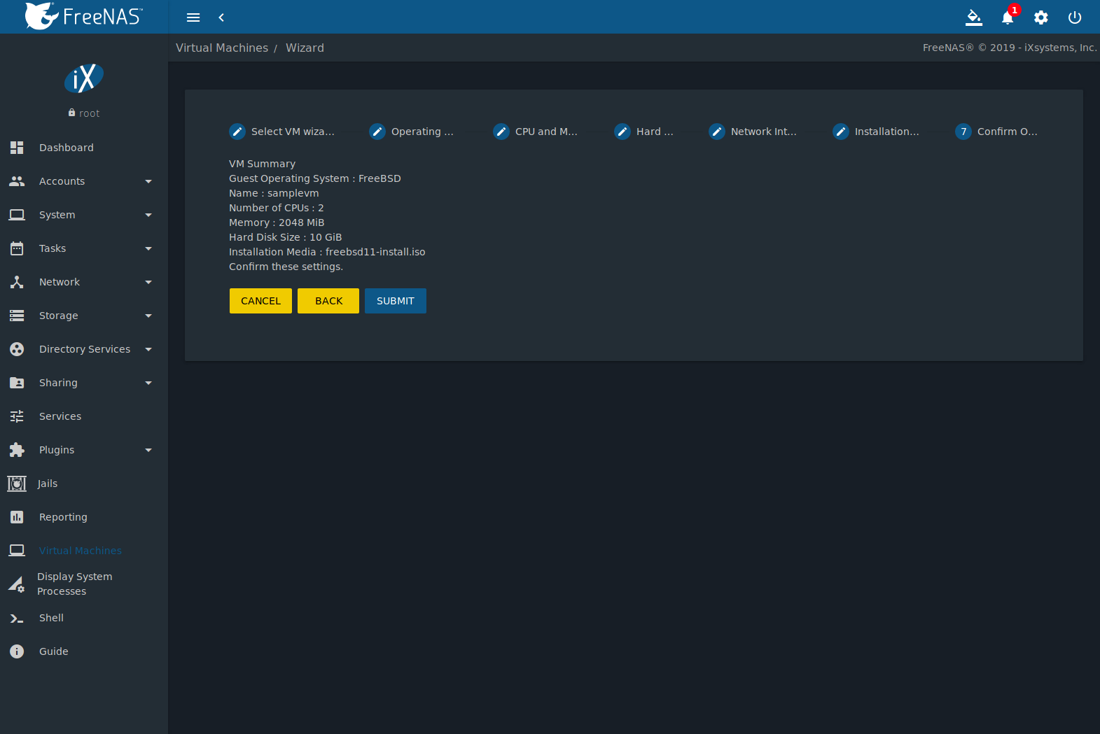
Fig. 16.1.2 Creating a Sample Virtual Machine
16.2. Adding Devices to a VM
Go to , (Options) , and click ADD to add a new VM device.
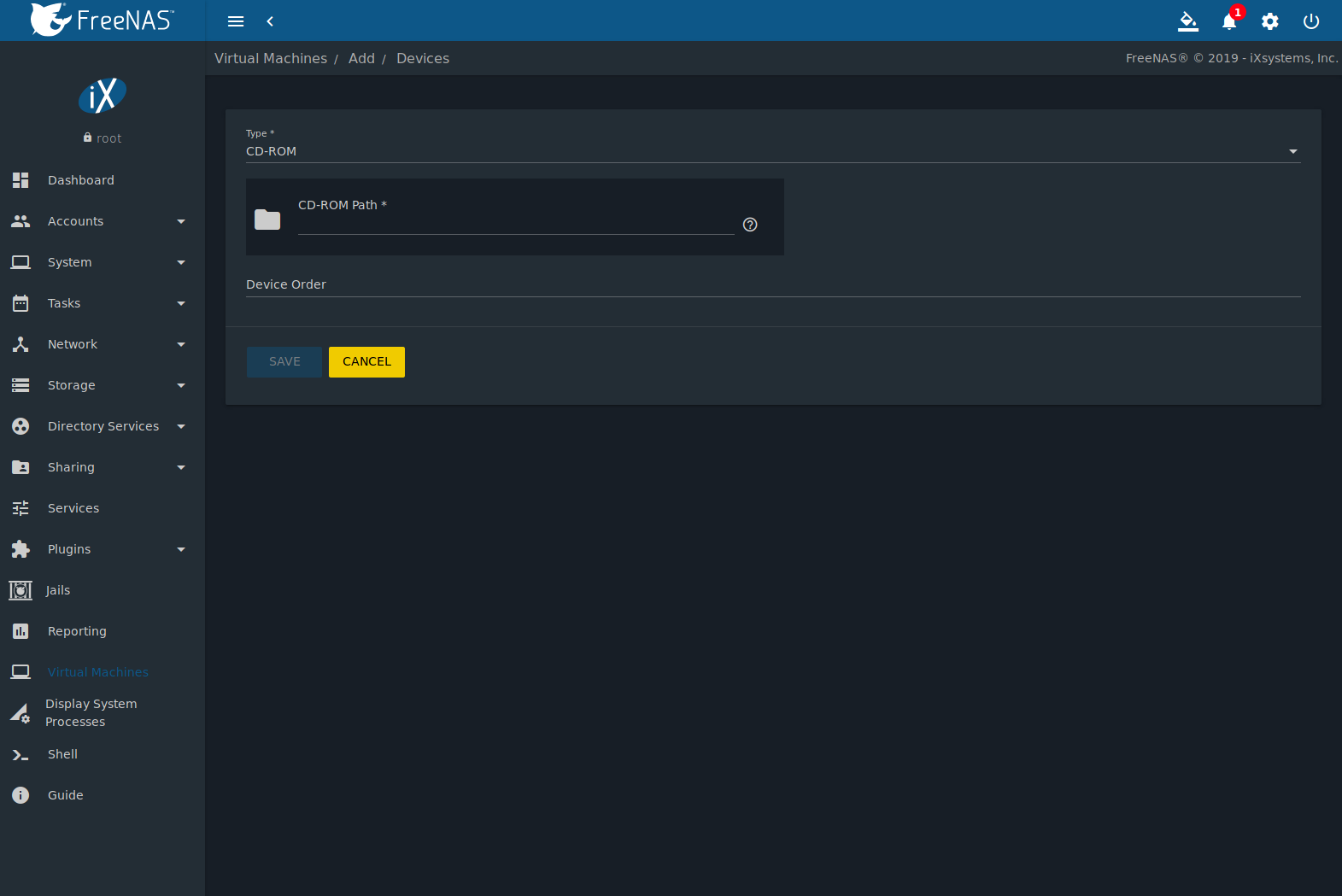
Fig. 16.2.1 VM Devices
Select the new device from the Type field. These devices are available:
- CD-ROM
- NIC (Network Interface Card)
- Disk Device
- Raw File
- VNC Interface (only available on virtual machines with Boot Loader Type set to UEFI)
(Options) is also used to edit or delete existing devices. Click (Options) for a device to display Edit, Delete, Change Device Order, and Details options:
- Edit modifies a device.
- Delete removes the device from the VM.
- Change Device Order sets the priority number for booting this device. Smaller numbers are higher in boot priority.
- Details shows additional information about the specific
device. This includes the physical interface and MAC address in a
NIC device, the path to the zvol in a DISK device, and the path
to an
.isoor other file for a CDROM device.
16.2.1. CD-ROM Devices
Adding a CD-ROM device makes it possible to boot the VM from a CD-ROM image, typically an installation CD. The image must be present on an accessible portion of the FreeNAS® storage. In this example, a FreeBSD installation image is shown:
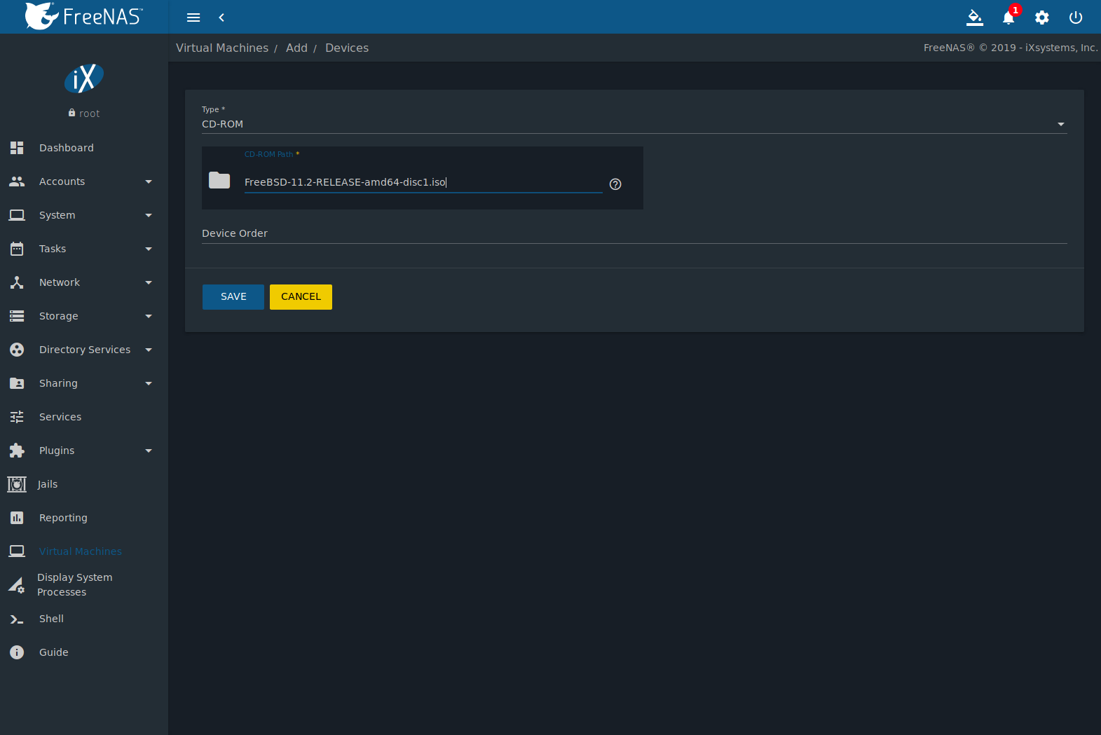
Fig. 16.2.2 CD-ROM Device
Note
VMs from other virtual machine systems can be recreated for use in FreeNAS®. Back up the original VM, then create a new FreeNAS® VM with virtual hardware as close as possible to the original VM. Binary-copy the disk image data into the zvol created for the FreeNAS® VM with a tool that operates at the level of disk blocks, like dd(1). For some VM systems, it is best to back up data, install the operating system from scratch in a new FreeNAS® VM, and restore the data into the new VM.
16.2.2. NIC (Network Interfaces)
Figure 16.2.3 shows the fields that appear after going to (Options) , clicking ADD, and selecting NIC as the Type.
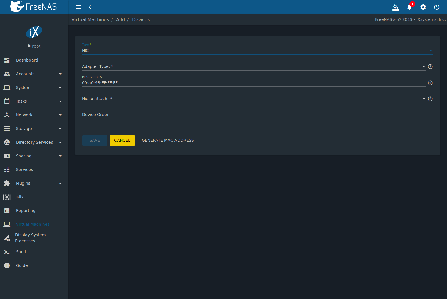
Fig. 16.2.3 Network Interface Device
The Adapter Type can emulate an Intel e82545 (e1000) Ethernet card for compatibility with most operating systems. VirtIO can provide better performance when the operating system installed in the VM supports VirtIO paravirtualized network drivers.
By default, the VM receives an auto-generated random MAC address. To override the default with a custom value, enter the desired address in MAC Address. Click GENERATE MAC ADDRESS to automatically populate MAC Address with a new randomized MAC address.
If the system has multiple physical network interface cards, use the NIC to attach drop-down menu to specify which physical interface to associate with the VM.
Set a Device Order number to determine the boot order of this device. A lower number means a higher boot priority.
16.2.3. Disk Devices
Zvols are typically used as virtual hard drives. After creating a zvol, associate it with the VM by clicking (Options) , clicking ADD, and selecting Disk as the Type.
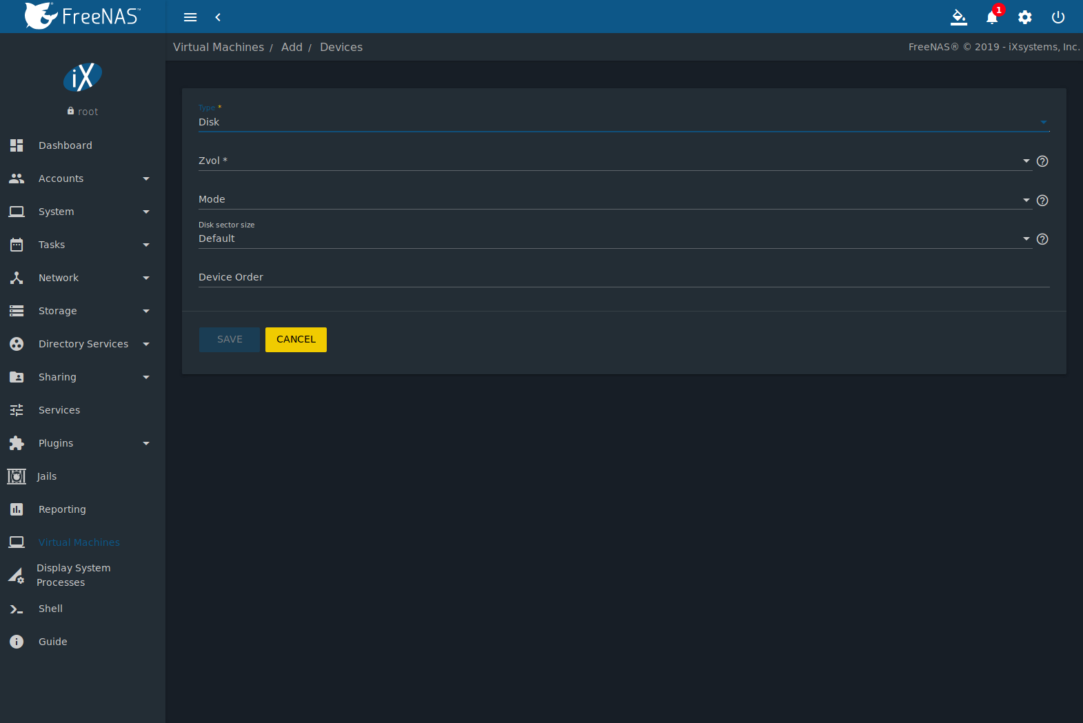
Fig. 16.2.4 Disk Device
Open the drop-down menu to select a created Zvol, then set the disk Mode:
- AHCI emulates an AHCI hard disk for best software compatibility. This is recommended for Windows VMs.
- VirtIO uses paravirtualized drivers and can provide better performance, but requires the operating system installed in the VM to support VirtIO disk devices.
If a specific sector size is required, enter the number of bytes in Disk sector size. The default of 0 uses an autotune script to determine the best sector size for the zvol.
Set a Device Order number to determine the boot order of this device. A lower number means a higher boot priority.
16.2.4. Raw Files
Raw Files are similar to Zvol disk devices, but the disk image comes from a file. These are typically used with existing read-only binary images of drives, like an installer disk image file meant to be copied onto a USB stick.
After obtaining and copying the image file to the FreeNAS® system, click (Options) , click ADD, then set the Type to Raw File.
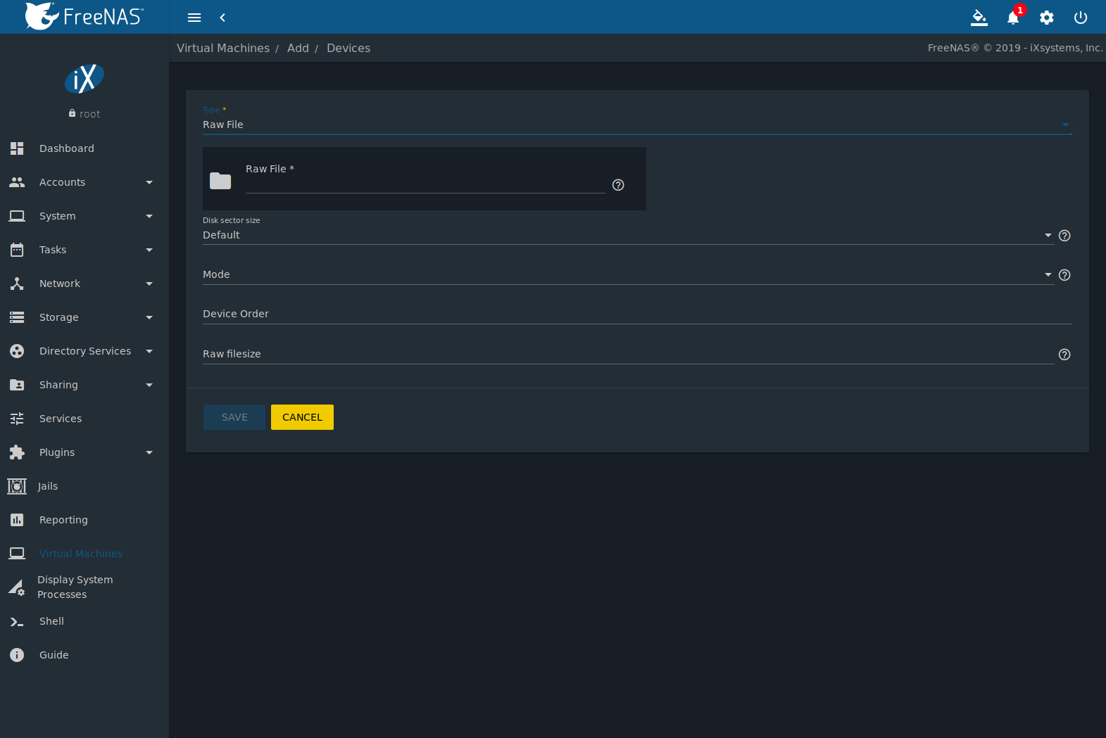
Fig. 16.2.5 Raw File Disk Device
Click (Browse) to select the image file. If a specific sector size is required, choose it from Disk sector size. The Default value automatically selects a preferred sector size for the file.
Setting disk Mode to AHCI emulates an AHCI hard disk for best software compatibility. VirtIO uses paravirtualized drivers and can provide better performance, but requires the operating system installed in the VM to support VirtIO disk devices.
Set a Device Order number to determine the boot order of this device. A lower number means a higher boot priority.
Set the size of the file in GiB.
A Docker VM also has a password field. This is the login password for the Docker VM.
16.2.5. VNC Interface
VMs set to UEFI booting are also given a VNC (Virtual Network Computing) remote connection. A standard VNC client can connect to the VM to provide screen output and keyboard and mouse input.
Each VM can have a single VNC device. A |dockerhost| does not support VNC connections. An existing VNC interface can be changed by clicking (Options) and Edit.
Note
Using a non-US keyboard with VNC is not yet supported. As a workaround, select the US keymap on the system running the VNC client, then configure the operating system running in the VM to use a keymap that matches the physical keyboard. This will enable passthrough of all keys regardless of the keyboard layout.
Figure 16.2.6 shows the fields that appear after going to (Options) , and clicking (Options) for VNC.
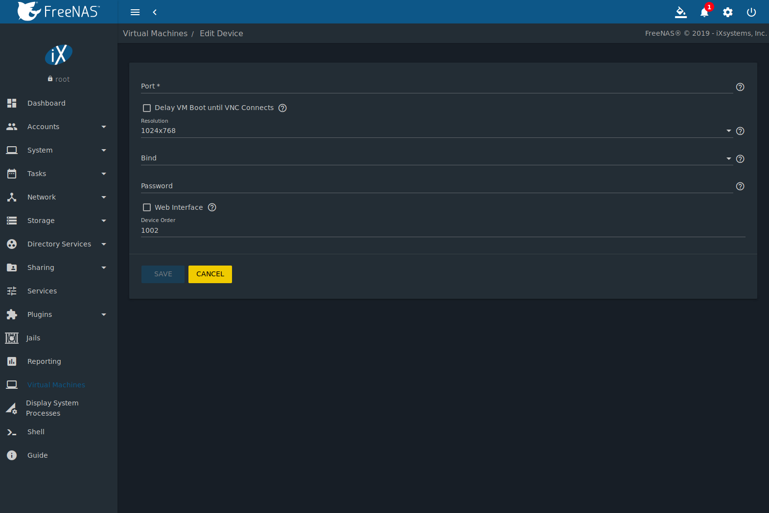
Fig. 16.2.6 VNC Device
Setting Port to 0 automatically assigns a port when the VM is started. If a fixed, preferred port number is needed, enter it here.
Set Delay VM Boot until VNC Connects to wait to start the VM until a VNC client connects.
Resolution sets the default screen resolution used for the VNC session.
Use Bind to select the IP address for VNC connections.
To automatically pass the VNC password, enter it into the Password field. Note that the password is limited to 8 characters.
To use the VNC web interface, set Web Interface.
Tip
If a RealVNC 5.X Client shows the error
RFB protocol error: invalid message type, disable the
Adapt to network speed option and move the slider to
Best quality. On later versions of RealVNC, select
,
click Expert, ProtocolVersion, then
select 4.1 from the drop-down menu.
Set a Device Order number to determine the boot order of this device. A lower number means a higher boot priority.
16.3. Docker VM VMs
Docker is open source software for automating application deployment inside containers. A container provides a complete filesystem, runtime, system tools, and system libraries, so applications always see the same environment.
Rancher is a web-based tool for managing Docker containers.
FreeNAS® runs the Rancher web interface within the Docker VM.
16.3.1. Docker VM Requirements
The system BIOS must have virtualization support enabled for a Docker VM to work properly. On Intel systems this is typically an option called VT-x. AMD systems generally have an SVM option.
20 GiB of storage space is required for the Docker VM.
For setup, the SSH service must be enabled.
The Docker VM requires 2 GiB of RAM while running.
16.3.2. Creating Docker VM
Figure 16.3.1 shows the Wizard that appears after going to , clicking ADD, and selecting Docker VM as the Virtual Machine (VM) Wizard type.

Fig. 16.3.1 Add Docker VM
Docker VM configuration options are described in Table 16.3.1.
| Screen # | Setting | Value | Description |
|---|---|---|---|
| 1 | Virtual Machine (VM) Wizard type | drop-down menu | Choose the type of VM to create. |
| 2 | Name | string | A descriptive name for the Docker VM. Alphanumeric characters and _
are allowed. |
| 2 | Start on Boot | checkbox | Set to start this Docker VM when the FreeNAS® system boots. |
| 3 | Virtual CPUs | integer | Number of virtual CPUs to allocate to the Docker VM. The maximum is 16 unless the host CPU limits the maximum. The VM operating system can also have operational or licensing restrictions on the number of CPUs. |
| 3 | Memory Size (MiB) | integer | Allocate this amount of RAM in MiB for the Docker VM. A minimum 2048 MiB of RAM is required. |
| 4 | Adapter Type | drop-down menu | Intel e82545 (e1000) emulates the same Intel Ethernet card. This provides compatibility with most operating systems. VirtIO provides better performance when the operating system installed in the VM supports VirtIO paravirtualized network drivers. |
| 4 | MAC Address | string | Enter the desired MAC address to override the auto-generated randomized MAC address. |
| 4 | Attach NIC | drop-down menu | Select the physical interface to associate with the VM. |
| 5 | Raw filename | string | Name of the disk image for the Docker Host to use as storage. |
| 5 | Raw filename password | string | Alphanumeric password added to the raw file. This is used to log in to the
Docker VM. The default is docker. |
| 5 | Raw file size | integer | Set the size of the new raw file. |
| 5 | Raw file location | browse button | Select a directory to store the new raw file. |
| 5 | Disk sector size | integer | Define the disk sector size in bytes. Default leaves the sector size unset. |
Choose the base options for the VM at each step of the wizard. Virtual CPUs is set to 1. Memory Size must be set to at least 2048 MiB.
The Network Interface step is automatically populated with system defaults. Customize these fields as necessary and press NEXT to continue.
The Storage Files section of the wizard contains options to create and store a raw file. Add a filename by typing an .img name in the Raw filename field. Enter a number of gigabytes for the Raw file size. Set the raw file location with the folder button or by typing a directory in the field.
The final screen of the Wizard displays the chosen options for the new Docker VM. Click SUBMIT to create the Host or BACK to change any settings. Click CANCEL at any time to return to the page.
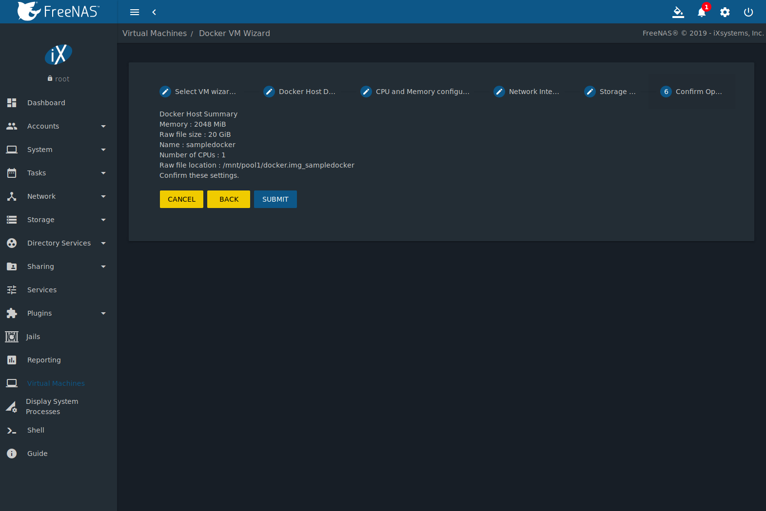
Fig. 16.3.2 Docker VM Configuration
Click (Options) and Serial to
log in to the Docker VM. Enter rancher for the user name
and docker for the password.
The default password is changed in the Devices by stopping the Docker VM, clicking (Options), and Devices. Click (Options) and Edit for the RAW device and enter a new value in the password field. Passwords cannot contain spaces.
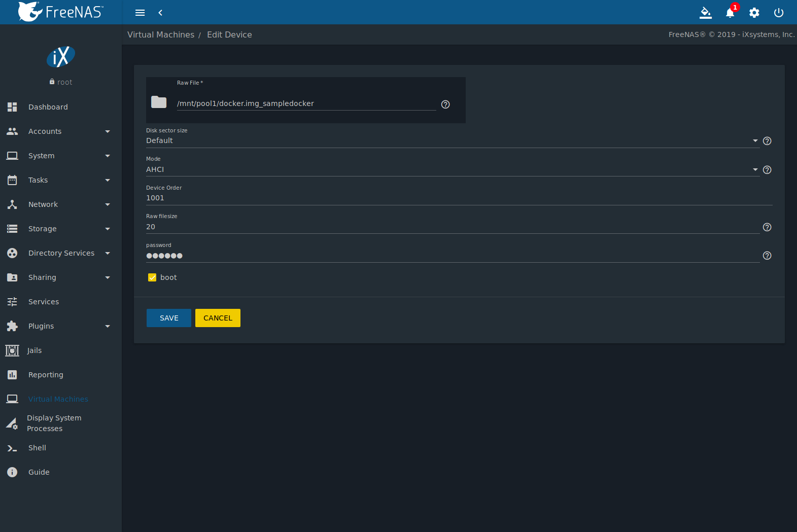
Fig. 16.3.3 Changing the Docker VM Password
16.3.3. Start the Docker VM
Go to and find the entry for the new Docker VM. Click (Options) and Start to boot the Docker VM.
A Docker VM can take several minutes to boot. Click (Options) and –> Serial to view the Docker VM activity during startup. Use this console to configure Rancher inside the Docker VM.
When the RancherOS console graphic is shown, press Enter to see
the ClientHost login: prompt. Enter the username
rancher and press Enter. If a custom password was set
in the raw file, enter it now. Otherwise, enter the default password of
docker. The [rancher@ClientHost ~]$ prompt is
shown.
16.3.4. SSH to the Docker VM
Go to
,
find the Docker VM entry, and locate the Com Port. Com
port names have the format /dev/nmdm1B, where {1B}
is unique for each VM.
Connect to the FreeNAS® server with an SSH client. The SSH service must be running with Login as Root with Password enabled.
At the FreeNAS® console prompt, connect to the Docker VM with
cu -l /dev/nmdm1B, replacing {1B} with the
Docker VM Com Port.
If the terminal does not immediately show a rancher login:
prompt, press Enter. The Docker VM can take several minutes to
start and display the login prompt.
16.3.5. Installing and Configuring Rancher
Ensure Rancher has functional networking and can ping an outside website.
[rancher@ClientHost ~]$ ping -c 3 google.com
PING google.com (172.217.0.78): 56 data bytes
64 bytes from 172.217.0.78: seq=0 ttl=54 time=18.613 ms
64 bytes from 172.217.0.78: seq=1 ttl=54 time=18.719 ms
64 bytes from 172.217.0.78: seq=2 ttl=54 time=18.788 ms

--- google.com ping statistics ---
3 packets transmitted, 3 packets received, 0% packet loss
round-trip min/avg/max = 18.613/18.706/18.788 ms
If ping returns an error, adjust the VM Network Interface and reboot the VM.
Download and install the Rancher server with sudo docker run -d --restart=unless-stopped -p 8080:8080 rancher/server.
If a Cannot connect to the Docker daemon error is shown,
enter sudo dockerd and try
sudo docker run -d --restart=unless-stopped -p 8080:8080 rancher/server
again. Installation time varies with processor and network connection
speed. [rancher@ClientHost ~]$ is shown when the installation
is finished.
Enter ifconfig eth0 | grep 'inet addr' to view the Rancher
IP address. Enter the IP address followed by :8080 into a web
browser to connect to the Rancher web interface. For example, if the IP
address is 10.231.3.208, enter 10.231.3.208:8080
in the browser.
The Rancher web interface takes a few minutes to start. The web browser
might show a connection error while the web interface starts. If a
connection has timed out error is shown, wait one minute and
refresh the page.
When the Rancher web interface loads, click Add a host from the banner across the top of the screen. Verify that This site’s address is chosen and click Save.
Follow the steps shown in the Rancher web interface and copy the full
sudo docker run command from the text box. Paste it in the
Docker VM shell. The Docker VM will finish configuring Rancher. A
[rancher@ClientHost ~]$ prompt is shown when the
configuration is complete.
Go to the Rancher web interface and click . When a host with the Rancher IP address is shown, configuration is complete and Rancher is ready to use.
For more information on Rancher, see the Rancher documentation.